- Joined
- Aug 17, 2008
- Messages
- 1,368
- Points
- 0
I need help building a blu-ray laser. I already have all of the needed parts, and I know all of the safety aspects of building the laser. This is not one of the million threads overflowing LPF where some new guy comes asking about what parts he will need to buy and what current he will need to set the driver to...etc.
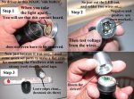
The problem is, I suck at DIY. I am using jayrob's MXDL tutorial, but I can't build my laser straight off the page. I need more detailed instructions. If anyone can help me with an in-depth step-by-step tutorial, please do. I would greatly appreciate your help, and I'm sure many other first-time laser builders will as well.
Tutorial link: http://www.laserpointerforums.com/forums/YaBB.pl?num=1217045236
Parts list:
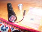
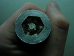
-3W MXDL host
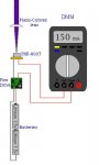
-Micro Flexdrive V2
-Jayrob heatsink
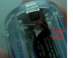
-PHR-803T diode pre-mounted in Aixiz module
I can't figure out how to attach more than one picture at a time straight from my computer, so I will just post a couple. I have better close-ups of everything, so just let me know if you need a better picture of a specific part.
Thanks,
Mark
The problem is, I suck at DIY. I am using jayrob's MXDL tutorial, but I can't build my laser straight off the page. I need more detailed instructions. If anyone can help me with an in-depth step-by-step tutorial, please do. I would greatly appreciate your help, and I'm sure many other first-time laser builders will as well.
Tutorial link: http://www.laserpointerforums.com/forums/YaBB.pl?num=1217045236
Parts list:
-3W MXDL host
-Micro Flexdrive V2
-Jayrob heatsink
-PHR-803T diode pre-mounted in Aixiz module
I can't figure out how to attach more than one picture at a time straight from my computer, so I will just post a couple. I have better close-ups of everything, so just let me know if you need a better picture of a specific part.
Thanks,
Mark