Welcome to Laser Pointer Forums - discuss green laser pointers, blue laser pointers, and all types of lasers

LPF Donation via Stripe | LPF Donation - Other Methods

Links below open in new window

ArcticMyst Security by Avery

Help on the Micro Boost drive

Joined
Jul 28, 2010
Messages
89
Points
0
Ok first of all Thank you so much Morgan for all the help, explaining (teaching) , an patience.

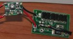
Ok here my problem I'll try an be very clear about it, I have the Rkcstr dummy load an I have set it up to Red and on the V1 drive I have it set to the current 390-750mA an on the MM I have it set it to 10A an im using a 14500 battery but when I test it, it just give me 1.20 an when I turn the nozzle to turn up the current it just shows 1.29.

Then I set my MM to 2000m and it shows a number one to the left side of the screen. Oh and the MM is not turn on, on te pictures.

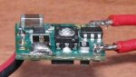
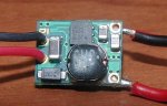
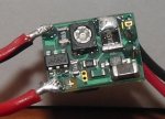
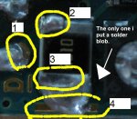
I have pictures but I have them all one by one cause I got close enough to get the details to show you guys but I know I have all the cables where they should be, negative with negative, and positive with positive. So if anybody has any idea what I'm doing wrong just post it. Or if I forgot to mention something just post it too.

:thanks:

-------------------------------------------------
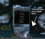
Ok sorry about the resistor i just saw a 2kohm but i also saw that they have a 1W 1ohm metal oxide resistor. So sorry about the bad info.
 

Attachments

  • V1 blob set.JPG
    V1 blob set.JPG
    44 KB · Views: 872
  • MM on 2000m.bmp
    495.2 KB · Views: 265
  • MM on 10A.bmp
    552.3 KB · Views: 269
Last edited:


Morgan

0
Joined
Feb 5, 2009
Messages
2,174
Points
0
Hi diodelaser and guys,

Just to say I have been trying to help here via PMs but we are still unsuccessful.

A few notes...

We are working with a Microboost here and a dummy test load from RKCSTR although I wasn't aware these used a 2K resistor as DL has told me through PM? :thinking: ... and I can't find mention of a 2K resistor in this link, even checking the, "User Instructions" download - Test Load KIT (AKA Dummy load, unassembled) - $5.75 : rkcstr.com, Micro-Drive and laser diode electronics

1 Ohm must be used to get a 1mV = 1mA reading.

From the pics, it seems the probe leads are in the right place but to get a 1 at the extreme left of the readout says to me that it's out of range.

The driver has apparently not been powered without a load so this must be something simple here. Testing across the resistor is, of course, the way to read mV but I am at a loss as to how to move forward. Any further help here would be appreciated.

DL seems to want to know what's going on here and isn't just being lazy in my opinion so hey, see how you go...

... Maybe you can help where I haven't been able.

I think some more pictures of the whole setup will help here. Readings actually being taken, probes in place, battery and driver connections...

Thanks all...

M
:)
 
Joined
Jul 28, 2010
Messages
89
Points
0
Hi diodelaser and guys,

Just to say I have been trying to help here via PMs but we are still unsuccessful.

A few notes...

We are working with a Microboost here and a dummy test load from RKCSTR although I wasn't aware these used a 2K resistor as DL has told me through PM? :thinking: ... and I can't find mention of a 2K resistor in this link, even checking the, "User Instructions" download - Test Load KIT (AKA Dummy load, unassembled) - $5.75 : rkcstr.com, Micro-Drive and laser diode electronics

1 Ohm must be used to get a 1mV = 1mA reading.

From the pics, it seems the probe leads are in the right place but to get a 1 at the extreme left of the readout says to me that it's out of range.

The driver has apparently not been powered without a load so this must be something simple here. Testing across the resistor is, of course, the way to read mV but I am at a loss as to how to move forward. Any further help here would be appreciated.

DL seems to want to know what's going on here and isn't just being lazy in my opinion so hey, see how you go...

... Maybe you can help where I haven't been able.

I think some more pictures of the whole setup will help here. Readings actually being taken, probes in place, battery and driver connections...

Thanks all...

M
:)
Thank you again Morgan ill try an put picture of the whole set up of the testing. I bough 1N4001 diodes an 1ohm resistor just in case the problem was coming from the dummy load. So ill see how it goes.
 
Joined
Dec 29, 2009
Messages
3,136
Points
63
With such a high resistance value as 20k, I would think that you'd have to have a very sensitive meter.

I believe the way we go at it is, starting from Ohm's Law (V=IR, where V is volts, I is current{amps}, and R is resistance) we get I=V/R. With a 1 Ohm resistor, the math is easy, I=V. With a 20k resistor, I=V/20,000, so you'd take the reading on the screen, in volts, and divide by 20,000. At those ranges, though, your meter would be reading mV at least, though, not to mention 20k would drastically affect how the load reacts. I think your best bet would be to build your own dummy load.

Any pics of the resistor on the dummy load you purchased? I find it odd that they state they use 1ohm resistors when your experience shows otherwise
 
Joined
Feb 7, 2010
Messages
360
Points
0
I am having a similar problem. I now have 2 drivers showing the same behavior. I too am using the rkcstr dummy load but mine was pre assembled. I did not experience any issues setting the current on my first microboost I used for my Kryton Groove but I went to build another laser out of an Ehgemus host (will be a 12x blu-ray) and had problems setting the driver current.

I am using the same range setting as the original poster here.

My symptoms with the dummy driver are...
- Pot does not make a difference.
- Current starts at the same current(actually it is measured by mv) each time it is powered on and then increases by a few mV ever second.

I bought 2 more microboost drivers a week or so ago and the first one of those I tested today is doing the same thing. I checked all the resistors on the dummy load with a Fluke 289 meter and they are all within spec. I have yet to touch the other driver until I figure this out.

BTW... the dummy load does use a 1ohm resister for the current check.
 
Last edited:

daguin

0
Joined
Mar 29, 2008
Messages
15,989
Points
113
We need to see pictures of the whole setup. The pot making no difference tells me that "something" is bridged where it shouldn't be.

You might try examining the driver with a 10-power loop.

Sometimes, when soldering the wire leads on, a VERY SMALL solder bridge may be left to an unwanted component.

Sometimes, the driver is heated to the point that the solder on one of the SM components melts, flows, and causes a bridge to an adjacent component.

It's happened to me ;)

Peace,
dave
 
Joined
Feb 7, 2010
Messages
360
Points
0
Thanks for the response. I can't seem to get any good pictures tonight. I will try again later tonight or tomorrow when the sun brightens up my den.

I looked at all the soldering points with a magnifying glass already but did it again to make sure and I could not see any solder points bridging anything else. They are all separated. The only bridge is the range setting for the r510 resistor to the adjacent solder pad. If anything has gone wrong with soldering it would have to be with that resistor I would guess. It looks ok though.
 
Joined
Feb 7, 2010
Messages
360
Points
0
Pics...

I didn't remove the extra flux off the board so it is reflecting in some spots making some spots look like solder when really it is a reflection so I had to take a few shots and use the best ones. The soldering on the connections on the battery lead side are temporary so they do not go through the board.

Edit: added pic d
 

Attachments

  • microboost-a.jpg
    microboost-a.jpg
    18.2 KB · Views: 845
  • microboost-c.jpg
    microboost-c.jpg
    48.3 KB · Views: 1,238
  • microboost-b.jpg
    microboost-b.jpg
    25.3 KB · Views: 1,695
  • microboost-d.jpg
    microboost-d.jpg
    31.3 KB · Views: 224
Last edited:

daguin

0
Joined
Mar 29, 2008
Messages
15,989
Points
113
30756d1291601940-help-micro-boost-drive-microboost-b.jpg

30752d1291601218-help-micro-boost-drive-microboost-.jpg


These do not appear to be the same driver :thinking:

30408d1289593456-help-micro-boost-drive-v1-blob-set.jpg


Do you have a spare diode you could hook up to the driver? Maybe the problem only exists in your test load.

Peace,
dave
 
Last edited:
Joined
Feb 7, 2010
Messages
360
Points
0
It is just flipped around. I only have one soldered up to the test load so I assure you they are of the same driver. The pic he has is the same thing too. I am confused why you think they are different.
 

daguin

0
Joined
Mar 29, 2008
Messages
15,989
Points
113
It is just flipped around. I only have one soldered up to the test load so I assure you they are of the same driver. The pic he has is the same thing too. I am confused why you think they are different.

V1blobset-1.jpg


microboost-b-1.jpg

microboost-a-1.jpg


The question about the spare diodes remains

Peace,
dave
 
Joined
Feb 7, 2010
Messages
360
Points
0
This is his picture. I placed numbers on them to clarify.

1. is the solder point for the laser diode. It looks like he didn't get solder on all of the solder hole.
2. One end of the R510 resistor. It looks like he accidentally touched the r510 diode with his soldering iron and left extra solder on it. Nothing there but extra solder stuck to r510.
3 is the other end of the r510 resistor.
4 is the pad that you connect 3 with to set the range on the driver.

The pictures show the same driver and components as mine. No extra diodes or resistors are there. Only extra or less solder.
 

Attachments

  • V1blobset-1-edited.jpg
    V1blobset-1-edited.jpg
    61.2 KB · Views: 210

daguin

0
Joined
Mar 29, 2008
Messages
15,989
Points
113
I know what they are. You asked why I thought they were different drivers. The circled portions are where the two drivers are different.

So they are not the same driver?

You have not answered my "spare diode" question.

Peace,
dave
 
Last edited:
Joined
Feb 7, 2010
Messages
360
Points
0
There is no spare diode. Which number do you see a spare diode? If you look at where area #4 is on my driver it is just a really big solder bridge to the end od the resistor at #3. He has much less solder ther so you can see the solder pad. Mine is just a big glob of solder. No diode or other component there except a resistor. There is no diode pictured at any of the locations that you marked. I am still confused where you seem to think there is a diode at any of those locations.

The drivers are the same. Only the amount of solder at the locations is different and he ran his wire to the diode (are #1) from the top side where i soldered it up through the solder hole from the other side.

#1 his driver he ran the wire on that side. #1 on my driver I ran the wire from the other side. That is just a solder joint with the wire coming up from the bottom. Nothing ther except solder and wire on both drivers.

#2 is just a blob of solder on his driver for the solder point of r510 resistor. Nothing there but solder and the end of r510. #2 on my driver is the same solder point but just the factory solder job for r510 resistor. No diode there at all on either driver... just a resistor end and solder.

This picture seems pretty clear to me.

30756d1291601940-help-micro-boost-drive-microboost-b.jpg
 
Last edited:

daguin

0
Joined
Mar 29, 2008
Messages
15,989
Points
113
There is no spare diode. Which number do you see a spare diode? If you look at where area #4 is on my driver it is just a really big solder bridge to the end od the resistor at #3. He has much less solder ther so you can see the solder pad. Mine is just a big glob of solder. No diode or other component there except a resistor. There is no diode pictured at any of the locations that you marked. I am still confused where you seem to think there is a diode at any of those locations.

The drivers are the same. Only the amount of solder at the locations is different and he ran his wire to the diode (are #1) from the top side where i soldered it up through the solder hole from the other side.

#1 his driver he ran the wire on that side. #1 on my driver I ran the wire from the other side. That is just a solder joint with the wire coming up from the bottom. Nothing ther except solder and wire on both drivers.

#2 is just a blob of solder on his driver for the solder point of r510 resistor. Nothing there but solder and the end of r510. #2 on my driver is the same solder point but just the factory solder job for r510 resistor. No diode there at all on either driver... just a resistor end and solder.

This picture seems pretty clear to me.

30756d1291601940-help-micro-boost-drive-microboost-b.jpg

Maybe I'm just not making myself clear enough

There are two separate questions before you

First question -- Is this
V1blobset.jpg


and this
microboost-a.jpg

the same driver?
Not are they both the same type of driver (MicroBoost).
Are they both the same driver?

Second question -- Do you have a spare laser diode there that you could hook up to the driver to test if the driver is actually working? It is possible that it is a problem with the test load. You could run a long open can or a long closed can red diode with the pot turned down. If the driver was OK and the problem was with your test load it would light the diode and you could turn it up and down. This would only risk a $12 diode instead of a $50 diode

Otherwise, I would go ahead and hook up the 445nm diode. They will take much more than the range you have it set to.

Peace,
dave
 
Joined
Feb 7, 2010
Messages
360
Points
0
One driver is diodelaser's. The pictures he posted is his (The darker picture is diodelaser's driver). Only the pictures I posted are my driver. They are different. We both just seem to have the same problem.

I have a 6x but i guess i like your idea of just using the 445nm diode and see what happens. I will monitor the current directly. Befor that I will Spend more time troubleshooting the test load but it seems to check out. Not under load all the diodes seem to drop the correct voltage. The 2 resistors on the test load also have the correct resistance. Continuity between the components check out too. Maybe a bad solder joint on the test load is causing problems somehow so I plan to measure the voltage drop of all my connections under load to see if there is a weak solder joint causing extra resistance under load. I will have to test that later tonight.

Thanks for the feedback on this. It is helping to keep me sane :).


Top