Welcome to Laser Pointer Forums - discuss green laser pointers, blue laser pointers, and all types of lasers

LPF Donation via Stripe | LPF Donation - Other Methods

Links below open in new window

ArcticMyst Security by Avery

Hello all...need a little help.

Joined
Dec 27, 2012
Messages
15
Points
0
Hello all, building my first laser. HOORAY ME! , Nice site you guys have here!

I did not like using idea of using the little driver boards out of the laser pointers. Instead I figured it would be better and a little more educational to make one.

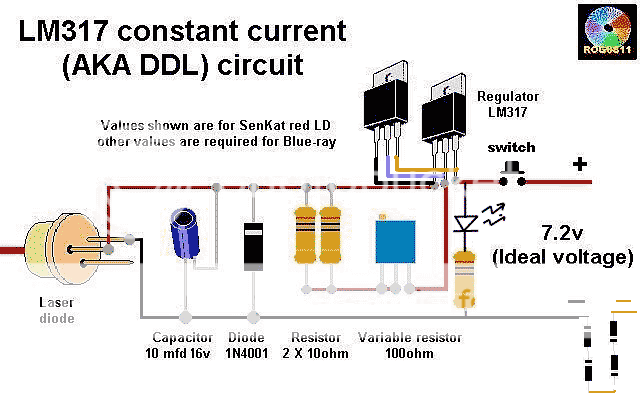
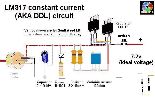
This is the one I have settled on, I like undertanding and being able to adjust the output with the resistors. With this, I will KNOW how much current is flowing to diode.

LM31720components01.jpg


My electronics skills are very rusty, I'm gettin old.

The above is simple enough, but I would like to add an on/off indicator light(green/red diode).

I'm not sure where to put it in the circuit.

could I put it in place of the 4001, with a 330-470ohm current limiting resistor??

Advice...thanks


Joined
Oct 26, 2007
Messages
5,438
Points
83
You should put the indicator light after the switch, but before the input to the regulator chip like this:

attachment.php


I'm using an LED in that arrangement. Remember to size the resistor according to Ohm's law. i.e. R_indicator = (V_in - V_led) / (I_led) . I_led will usually be 10-20mA, and V_led will depend on the LED's specifications.
 

Attachments

  • ddl_with_indicator.png
    ddl_with_indicator.png
    25.5 KB · Views: 7,284
Joined
Dec 27, 2012
Messages
15
Points
0
First off, thank you for your time.

It works and works well, but I have a heat problem. The system is tied to 12Volts and the LM317 heats up, heats up to much. So, I am looking for ways to cut down the heat. I have come up with 2 solutions, but wanted to ask before I moved forward.

solution 1 ... Put 2 LM317's in parallel, I don't know if this is LEGAL, I know it works with 7805's. See photo.

ddl_with_indicator_zps642eaf54.png


Solution 2, add several diodes to drop the 12 Volts down to about 6-7 volts, so 317 does not have to handle the burn off heat...


Thanks again
 
Last edited:
Joined
Oct 26, 2007
Messages
5,438
Points
83
You could do that, but I'd seek out a lower voltage power source rather than add components and waste power to drop voltage.
 
Joined
May 10, 2011
Messages
1,878
Points
48
also just add a heatsink for your lm317 if that is the only supply you have available

also before you hook it up to your laser diode short the output as to drain the capacitor. otherwise when the cap drains upon connection you could damage your diode
 
Joined
Oct 26, 2007
Messages
5,438
Points
83
Or just omit the capacitor from that circuit altogether. Put it before the LM317 if you must, but after it doesn't do much and might actually end up frying your stuff.
 
Joined
Sep 20, 2008
Messages
17,622
Points
113
Yeah... that 10uF cap is useless on a DC input supply.
Your DC input MUST be cleanly filtered if it is not supplied
by batteries.

A small .01 to .1 Cap will protect better against any transient
spikes but you still need to discharge that cap BEFORE you
connect you LD or like BB said just remove it completely.

As to the heat...-----> Heatsink....and maybe a fan even if
you parallel the LM317.
One other way is to use an appropriately sized input resistor
to take some of the heat but the LM317 still need a heatsink.


Jerry

You can contact us at any time on our Website: J.BAUER Electronics
 
Joined
Dec 27, 2012
Messages
15
Points
0
Thanks all,

I have went with the dual 317's, and a few diodes on both the + and the - to drop the voltage ..don't recall but I think I added about 6 4001's. Also used about 5 pre 1982 (REAL COPPER) pennies for heat sink. Seems to take about 10min to get warm, I think this will work out fine after mounted to more metal. FYI, this project needs to be a CW setup..Making my own version of a Pulsar940.

Sorry Bionic, but I did not go with your placement of the LED and resistor for a few reasons.
1) The V-in may change sometime in the future.
2) We have a known Voltage and Current, out of the 317. 2-2.2v and 250ma. Seems silly not to take advantage of it.

I think an LED is perfectly happy with 2 volts and 10-30ma, I could always tweak the 2 resistors or pot, to get back that 20ma.
Not having the LED specs(pulled led), I tried a 500ohm..to dim, popped in a 330ohm, just fine.

Besides, If my thinking is correct :undecided: The simple circuit below is how I learned to discharge a cap.

Is not the lower one the exact same, only with a LED diode, still a one way device. Would it still not discharge that cap?
My thinking is it still serves the original purpose + a indicator light + cap discharge and still saves the LD if power is hooked up wrong..


Discharging-a-capacitor_zpsb4b492b7.png


In effect a cap discharge circuit built right into the original ???

Please, I do want to UNDERSTAND it....and the error of my ways...


ddl_with_indicator_zpsb3d38993.png
 
Last edited:
Joined
Oct 26, 2007
Messages
5,438
Points
83
You should put the indicator LED before the regulator, by the switch, otherwise the current coming out of the regulator will be split between the LED and the laser. Also, just axe the capacitor altogether from the circuit. Whoever first designed the circuit above didn't understand that the LM317 is already excellent for preventing transients from affecting the laser diode; so the capacitor is unneeded. The only thing that capacitor is going to do is help you accidentally fry your laser diode.

I wouldn't have any other components besides the laser diode and the current regulating circuitry after the voltage regulator. If you really want the capacitor, or indicator LED, put it before the voltage regulator, but after the switch, but not after the voltage regulator.

Also, when we say "discharge the cap" we mean you should short the leads before soldering the laser diode to prevent any residual charge from entering the laser diode. You should do this anyway with any driver you're hooking to your laser diodes. Still, remove capacitor altogether. It's not going to help things.
 
Joined
Dec 27, 2012
Messages
15
Points
0
Ok, minor circuit changed again...

LED (guess at 20ma) over Vin+ 12v with a 560ohm resistor. Looks fine.

My reason for wanting to keep the cap, is my setup is just a little diff.

I don't have a 100ohm pot.
Instead, I put a switch in to switch another 10ohms in parallel.
So I just have a low at 250ma, and a high of anout 380ma.

I don't think I'll ever need to hit it at 380, but its there.


I figure the Cap would smooth it out a bit.

But if you still say to dump it, Its gone..

thanks


Top