Hello all,
I am I guess what you would call an enthusiast with a sparse number of relatively cheap lasers which keeps dwindling which I've been meaning to replenish, among them is a 100mw 405nm purchased from O-like around 3 years ago or so.
It still works fine, though it is definitely not TEM00 nor is it in the best shape aesthetically but it works nonetheless. Moving forward, a friend of mine dropped it and separated the aperture/diode segment from the rest of the housing. I managed to put it back together easily enough and it still worked fine, however it came apart again later and with that, a black wire also became disconnected.
I figured I'd still try and put it back together nix the wire, and of course it doesn't work.
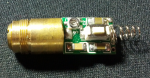
What I'm just wondering is if anyone here could tell me what the wire connects to. I can guess where it was originally connected to the board (there is one corner on the bottom/battery end that has solder, the other is empty) but what I don't know is where/what the exposed end actually connects to. Attached is a pic of the diode+driver if it helps at all.
It may not necessarily be worth fixing, but I'd like to if I can. I also had the misfortune to lose the little bugger when I realized this would be a good place to ask, I do have plenty of other random wiring to use in place of it though, and I do have experience soldering and working with relatively small electronics. I just can't really read diagrams very well at all.
cheers
I am I guess what you would call an enthusiast with a sparse number of relatively cheap lasers which keeps dwindling which I've been meaning to replenish, among them is a 100mw 405nm purchased from O-like around 3 years ago or so.
It still works fine, though it is definitely not TEM00 nor is it in the best shape aesthetically but it works nonetheless. Moving forward, a friend of mine dropped it and separated the aperture/diode segment from the rest of the housing. I managed to put it back together easily enough and it still worked fine, however it came apart again later and with that, a black wire also became disconnected.
I figured I'd still try and put it back together nix the wire, and of course it doesn't work.
What I'm just wondering is if anyone here could tell me what the wire connects to. I can guess where it was originally connected to the board (there is one corner on the bottom/battery end that has solder, the other is empty) but what I don't know is where/what the exposed end actually connects to. Attached is a pic of the diode+driver if it helps at all.
It may not necessarily be worth fixing, but I'd like to if I can. I also had the misfortune to lose the little bugger when I realized this would be a good place to ask, I do have plenty of other random wiring to use in place of it though, and I do have experience soldering and working with relatively small electronics. I just can't really read diagrams very well at all.
cheers