Welcome to Laser Pointer Forums - discuss green laser pointers, blue laser pointers, and all types of lasers

LPF Donation via Stripe | LPF Donation - Other Methods

Links below open in new window

ArcticMyst Security by Avery

Flexdrive output issue

Joined
Aug 26, 2008
Messages
387
Points
18
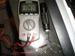
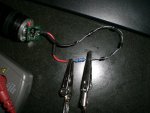
I have a flexdrive hooked up to 3 x AAA batteries. For a dummy load I have 4 x 1n4001 diodes and a 1/2 watt 1K Ohm resister. With the dummy load connected, I get about 7 volts off the diode side of the PCB. When connected between the diodes I get about 2.55 v's. When I check for current on either side of the resister I can only get a max of approx 270 mV. The 270 mV is achieved by turning the pot. The range is about 115 - 270 mV. I would like to p0wer an open can diode (red) at about 420 mV. Why am I not able to achieve this from the flexdrive? What am I missing? Thanks in advance.
Alan


ArRaY

0
Joined
Jul 18, 2008
Messages
281
Points
0
Keep in mind that you measure across a 1k ohm resistor, not a 1 ohm one.
I=U/R. Also, you gotta measure the voltage across the resistor.
Couldn´t see from you post what you where measuring b/c you seem to be mixing up mV and mA...

ArRaY
 
Joined
Aug 26, 2008
Messages
387
Points
18
Sry...I should have said mA. I am placing the MM's leads on each side of the resistor. + on the + side and - on the 1n4001 diode side which leads to the - side of the PCB. My dummy load is 4 x 1n4001 diodes in line with the resistor.
 
Joined
May 2, 2008
Messages
2,025
Points
63
ArRaY said:
Keep in mind that you measure across a 1k ohm resistor, not a 1 ohm one.
I=U/R. Also, you gotta measure the voltage across the resistor.
Couldn´t see from you post what you where measuring b/c you seem to be mixing up mV and mA...

ArRaY
with what he's doing, the mV will equal the mA 1:1
 
Joined
Aug 26, 2008
Messages
387
Points
18
Does anyone else have an idea? I switched out the flexdrive and got the same result. Are the standard AAA's just not putting out enough juice. These are just standard radio shack alkalines. I measured 4.6v's coming direct from the flashlight body to the flexdrive. i replaced the batteries with brand new and was able to get 300 mA's from the output of the flexdrive. Anyone else know the issue?
 

rkcstr

0
Joined
Dec 1, 2007
Messages
1,368
Points
0
I think you're using a MUCH too large resistor on there and willing to bet that it is why you're getting strange readings. 270mV through a 1Kohm resistor means the driver's only putting out 0.27mA (Ohm's Law, V = I / R), probably because to push 500mA through 1Kohm would require 500V from the driver!

Try finding a smaller resistor to put in series... 1ohm is easiest, since it would be 1mV = 1mA, but you could use like a 10ohm or whatever that's relatively low resistance and use that pesky Ohm's Law yourself.
 

jayrob

0
Joined
Sep 21, 2007
Messages
9,862
Points
113
Here's a good diagram for setting up a 'dummy load' from rog8811. This shows a DDL driver, but it is the same for a FlexDrive.
http://www.laserpointerforums.com/forums/YaBB.pl?num=1197651171#1

As far as your question on the AAA batteries, as long as you have them connected properly (in series), there should be at least 4.5 volts. Perfect for the FlexDrive.

The new FlexDrives have two settings as well. Look at the picture showing the 'high range jumper' in the instruction sheet:
http://hacylon.case.edu/laser/lavadrive2/Micro_Flex_Drive_User_manual_ V2.pdf

But rkcstr is correct, you need a 1 ohm resistor... not a 1K ohm. (Or, no resistor at all. Just use mA's setting on your DMM instead of mV)
Jay
 

Ryo

0
Joined
Aug 11, 2008
Messages
134
Points
18
HumanSymphony said:
[quote author=ArRaY link=1220554179/0#1 date=1220555058]Keep in mind that you measure across a 1k ohm resistor, not a 1 ohm one.
I=U/R. Also, you gotta measure the voltage across the resistor.
Couldn´t see from you post what you where measuring b/c you seem to be mixing up mV and mA...

ArRaY
with what he's doing, the mV will equal the mA 1:1[/quote]

Only if your talking about using the 1 Ohm load.

Definitely change it to 1 Ohm. I use 1 Ohm 1watt rated resistor.

Also there's 2 settings in the FlexDrive. One is low which start at 60 mA to (I think) 110mA. Then there's the location to jumper which puts you in the high power side.. which brings it up to somewhere in the 400 mA range (if I remember correctly). Look at his instructions on what to jumper.
 
Joined
Aug 26, 2008
Messages
387
Points
18
Ok...I feel really stupid and I'll tell you why in a second. First though Jay sent me a 3 ohm 1 watt resistor with his heatsink. I replaced the 1K ohm resistor with the 3 ohm in my dummy load. Do I now need to multiply the mA shown on my MM by 3 to get the true current? For example, I was able to tune the pot for 140 mA with the 3 ohm resistor, do I then multiply the 140 x 3 to get the results without the resistor? Meaning when I hook up the LD it will be receiving 420 mA of current? If this is true then the mistake cost me 2 open can red diodes. With the 1K Ohm resistor I was turning the pot till it maxed out, with the 3 AAA batteries that was about 270mA and with 2 CR-123 I was able to get the driver to put out about 390 mA. When I connected the LD...I'm guessing they fried because I was giving it like a gazzillion mA's. That explains why the 2R7 on the flexdrive was too hot to touch :D Let me know...but so far this has cost me about 60 bucks...flush gurgle gurgle :(
 

ArRaY

0
Joined
Jul 18, 2008
Messages
281
Points
0
Let me re-state, that the formula is I=U/R. That means, if you use a 3 ohm resistor, you get I=V/3.
Using your values, you can solve it. I=140/3 = 46,66666.....

Again, it is not clear what you are measuring and what scale you are using.
If you want to measure the current going into your diode, you have 2 possibilities.

First, you could measure the _Voltage_ _across_ the 3 ohm resistor, using the mV or V scale on you meter, and then calculate the mA,
or you could measure the current directly with your meter. You would then have to create a break in the electrical path, and brigde that break with your meter, set to mA or A scale. However, this will not always be the best option, as you need to create the break and many/most DMM´s(right?) are only fused to about 200mA.Unless you´re not using the 2A option, but I don´t know its accuracy.

ArRaY
 
Joined
Aug 26, 2008
Messages
387
Points
18
I don't follow the logic.  Isn't the resistor providing 3 ohm's of resistance, so if I am measuring the current going across the 3 ohm resistor using the mA setting on my MM and get 140 mA's then the current going to the LD without the resistor would be 3 times that or 420 mA's?  In other word's, if I was using a 1 ohm resistor then 1 mA = 1 mV.  So since I am using a 3 ohm resistor then I need to multiply my result by 3 versus dividing?  I'm thinking if I removed the 3 ohm resistor then I would be getting 3 times the current? I look at the formula this way...V=IR. So the Volts in Mv=140mA x 3 ohms.
 

ArRaY

0
Joined
Jul 18, 2008
Messages
281
Points
0
Forgot to say, if your going to measure current directly, you have to measure it without the resistor.
It is there in the first place, to eliminate the need to create a break in the circuitry, to measure mA as you can measure mV across it and then calculate the current.

ArRaY
 

rkcstr

0
Joined
Dec 1, 2007
Messages
1,368
Points
0
OK... first, do you have DrLava's Flexdrive or my Micro-Drive?  You mentioned a 2.7ohm resistor, which mine has, but I don't know about the Flexdrive?

Anyway, I think you have some misconceptions about all of this.

First, current is the flow of electrons (electricity), while voltage is the electrical potential.  You can measure the voltage, similar to air pressure or water pressure, with an external source, like a gauge or for electricity, a voltmeter.  BUT, to measure flow, its basically the "volume" of eletrons passing any point in a given amount of time... you can only measure that by flowing electrons through the instrument.  So, if you just put an ammeter (ie multimeter set to A or mA) in parallel (connected across) a resistor, the meter's internal resistance is going to act as a parallel resistor and share the current with the resistor, not giving the full current to the meter.  You need ONLY the meter in line with the current to measure it fully.

The reason we say to measure the VOLTAGE across a resistor is because if you measure the voltage across a resistor of a known resistance, by Ohm's Law (already quoted here multiple times over), you can calculate current.  So, if you have your 3 ohm resistor, and you measure the voltage across it, you can calculate current as follows (for example):

V = I * R
V / R = I
I = 0.15V / 3ohms
I = 0.050A = 50mA

EDIT:  Nevermind about the question about the flexdrive... I see now you were talking about the inductor on there... its 2.7uH, lol.  It's not a resistor, but a coil of wire wound around a ferrous core.
 
Joined
Aug 26, 2008
Messages
387
Points
18
Well a picture is worth a thousand words...and sorry to be a pita but I'm still confused. I'll post 3 pictures.
This is my DMM set to mA and it is reading 139mA with the leads across the 3 ohm resistor. If I want to drive an open can red diode at 420mA, what should I be reading in my DMM???
 

Attachments

  • CIMG0603.JPG
    CIMG0603.JPG
    259 KB · Views: 83
Joined
Aug 26, 2008
Messages
387
Points
18
Picture showing close up view of dummy load.
 

Attachments

  • CIMG0604.JPG
    CIMG0604.JPG
    287.7 KB · Views: 85


Top