Welcome to Laser Pointer Forums - discuss green laser pointers, blue laser pointers, and all types of lasers

LPF Donation via Stripe | LPF Donation - Other Methods

Links below open in new window

ArcticMyst Security by Avery

Find the weak spot in this laser driver

Joined
Apr 23, 2013
Messages
17
Points
0
Hello folks !

I recently have completed my laser engraver with an dvd burner diode.
It runs at 300mV blabla.

But I have a problem with it. The driver is made by groover.
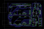
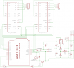
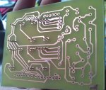
This is the schematic and the layout.

However I have some issues. And I guess it is because of the driver. I mean how I did it (solder/parts/replaceables etc)

attachment.php


attachment.php


C1 0,1uF
C2 47uF 25v electrolytic
D2 SA15A
IC1 LM317
R1 3,9 ohm
R3 51 ohm
R4 1 K ohm
R6 500 ohm TRIM POTENTIOMETER

D1 1N4148
R2 2,2 K ohm
T1 2N2222
VR05R051 RR1A - relay (digi-key = 306-1019-ND)
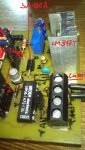
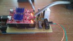
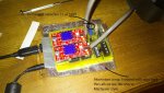

My remake

attachment.php


attachment.php


attachment.php


attachment.php


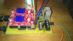
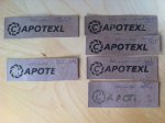
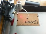
And this is how the problems looks

attachment.php


The problem is that the laser sometimes doesn't turn off as it should when it is moving to another engraving point. So it leaves an unwanted line on the working piece. When re-runnning it the errors occur at ((slighlty)) offset positions
I sometimes notice, that the laser turns off just in about the middle of the none-engraving move. Just like the relay gets the command much too late.
On the other hand it is sometimes really accurate with turning the laser off.

In my remake I switched the SA15A into an SA180A. This one is just tolerates 180V instead of 15V. Shouldn't be the problem.

Also C1 (the 0,1uF capacitor) is not as big as Groovers but it still tolerates up to 15V.

My guess was EMF interferences. So I tried to get all the cables for motors and the laser at an 90° angle to each other as good as it gets. This didn't fix it.
I replaced all the cables with shielded USB cables. Didn't help as well.

I got the advice to put another empty pcb or (isolated) metal sheet between the Arduino and the laser shield. Havn't tried this yet.


What do you guys think ?
 

Attachments

  • board_design.jpg
    board_design.jpg
    71.1 KB · Views: 2,045
  • schematic_groover.png
    schematic_groover.png
    69.9 KB · Views: 2,163
  • DSC_02752.jpg
    DSC_02752.jpg
    118.8 KB · Views: 1,704
  • DSC_0287_2.jpg
    DSC_0287_2.jpg
    181.9 KB · Views: 1,971
  • DSC_0071_usb.jpg
    DSC_0071_usb.jpg
    145.3 KB · Views: 1,488
  • DSC_0150_bottom.jpg
    DSC_0150_bottom.jpg
    167.6 KB · Views: 1,586
  • DSC_0112_fehler.jpg
    DSC_0112_fehler.jpg
    146.1 KB · Views: 1,774


Joined
Apr 23, 2013
Messages
17
Points
0
wrong forum sorry !!!

could someone please move this to the "Drivers" subforum ?

I skipped over it. Sorry
 
Joined
Sep 12, 2007
Messages
9,399
Points
113
How fast are you scanning? Looks to me like C2 is way too high. Try <1µF instead.
 
Joined
Apr 23, 2013
Messages
17
Points
0
The speed varies from 50mm/sec (engraving) to 500mm/sec (feed). Those numbers are quite theoretical I think because 500mm/sec are pretty fast and the actual movement speed seems to be below that. Anyways these are the software settings and the caligrated values are pretty acurate.

This is an older video with a pen attached and the speed should be 150-200 mm/sec to give you an impression of the movement speed.


I will try a smaller capacitor and report back.
Thanks.
 

DTR

0
Joined
Jun 24, 2010
Messages
5,684
Points
113
The speed varies from 50mm/sec (engraving) to 500mm/sec (feed). Those numbers are quite theoretical I think because 500mm/sec are pretty fast and the actual movement speed seems to be below that. Anyways these are the software settings and the caligrated values are pretty acurate.

This is an older video with a pen attached and the speed should be 150-200 mm/sec to give you an impression of the movement speed.

I will try a smaller capacitor and report back.
Thanks.

Here you go fixed your video.:beer:
 
Joined
Apr 23, 2013
Messages
17
Points
0
Thank you DTR.

I just finished a test run with a 1uF cap. Didn't fix it.

I although put a folded aluminium layer between the shield and the arduino. Isolated with two layers of duct tape on each side.
This did not fix the problem either.

I guess I have to rebuild the shield. Maybe some solder joints are bad or the traces are not placed well and therefore cause interference. I did draw those tracers by hand with a permanent marker.

attachment.php
 

Attachments

  • DSC_0132(1)_klein.jpg
    DSC_0132(1)_klein.jpg
    204.4 KB · Views: 1,617
Last edited:
Joined
Apr 23, 2013
Messages
17
Points
0
I am a bit overwhelmed by the abundance of drivers here.
The above driver should work without flaws but my built doesn't.
However the shield has an external driver connector. Maybe using this jumper I could try another driver.

I already built the one from Life long experimenter - It can be done. Tested with batteries and the lasre. It works. Nice.
I hooked it up to the shield's external connector. The problem is I can only turn it on but not off. Needed to pull the emergency-off pin on the shield to turn it off.

I guess this one is not TTL compliant ?
Sorry I still do not have a clue what this TTL actually is or if this driver from rog8811.com does "have" it ?

Please light me up.
 
Joined
Dec 23, 2008
Messages
3,948
Points
63
ttl is 5v on 0v off or vise versa. it sends this signal high speed. There are lots of ttl drivers on ebay.

michael.
 
Joined
Sep 12, 2007
Messages
9,399
Points
113
The only other two possibilities are a relay problem or a problem with the signal you're using to drive the relay.
 
Joined
Apr 23, 2013
Messages
17
Points
0
Yeah Cyparagon, I guess the relay really is a problem. I will try to replace it with a FET.

Onther thing I did not mention. As work surface I replaced the wooden board I had first with a trimmed piece of metal from an old pc case. I used neodynium magnets to hold the work piece in place. The laser and its cable move in a distance of about 10cm above the magnets. The magnets are of mixed sizes. From pea-sized to hdd magnets.

I replaced the metal board with the old wooden board and removed all the magnets.
Now these false lines are reduced by about 70-80% but they are still there. So this helped alot but it is still from perfect.

The FET should do the rest.
How should I dimension it ? Any hints
 
Joined
Apr 23, 2013
Messages
17
Points
0
UPDATE:

I reduced the engraving speed to <100mm/sec and from the first looks of it that fixed the false lines. The areas are now perfectly engraved.
I guess I could put the metal board with its magnets back in.
 
Joined
Apr 23, 2013
Messages
17
Points
0
I have another update in that matter.
I made several test runs with different feed rates.

See pictures

attachment.php


You might wonder why I havn't finised the test series.

I drove the diode with 300mV / 300 mA.
This is a bit to much for a DVD burner diode I guess. Found out that this kind of diode is called Small Closed Can.
Engraving areas is a real stress test at 300mV.

The laser point changed from

(Picture taken at night)
attachment.php


to (but still engraving); Picutre made at daylight

attachment.php


to

attachment.php


The last picture shows the diode as it cannot burn anything. Not even black craft foam. So I guess I killed it. I doubt there is a way to "repair" it.
Setting the diode to 200-250mV (with dummy load) should not be exceeded.
LOC (Long open can) should be better and are available for 10 € on ebay. Hmmm. Whats your expert opinion ?
 

Attachments

  • IMG_0048.jpg
    IMG_0048.jpg
    194.9 KB · Views: 1,341
  • step_1.jpg
    step_1.jpg
    188 KB · Views: 1,324
  • step_2.jpg
    step_2.jpg
    169.6 KB · Views: 1,713
  • step_3.jpg
    step_3.jpg
    179.4 KB · Views: 1,350
Last edited:
Joined
Dec 29, 2009
Messages
3,136
Points
63
What about 405nm? Folks here seem to swear by its "burning" ability, and I believe you can get pretty high powers in single mode cavities, and in a closed can for better environmental protection :)
 

DTR

0
Joined
Jun 24, 2010
Messages
5,684
Points
113
Last edited:
Joined
Apr 23, 2013
Messages
17
Points
0
I would rather stay with those SCC DVD burner or LPC-826s. Just my opinion.

But about my question above ?

Could you tell why I fried my diode ?
1) I drove it at 300mV/300mA for long and excessive area engraving.
2) I maybe could have re-plugged the laser diode to the board without prior shorting the C2 capacitor.

What do you think was the killer ? And why is it still glowing ? I thought frying a diode would kill it "full"


Top