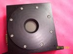
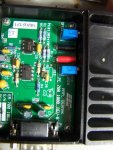
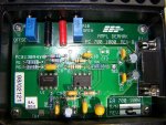
I was just wondering if anyone might know what the pins are for on one of these power sensors, I looked inside it, and it appears that it needs a + and - power source, but I dont know what else it needs to be used. Anyone know anything about one of these? It came from a dermaK medical laser, same one I got the co2 and yag from. heres some pics of it:
LPF Donation via Stripe | LPF Donation - Other Methods
Links below open in new window
ArcticMyst Security by Avery


You are using an out of date browser. It may not display this or other websites correctly.
You should upgrade or use an alternative browser.
You should upgrade or use an alternative browser.
figuring out pinouts on a laser power sensor
- Thread starter disma
- Start date


- Joined
- Sep 20, 2008
- Messages
- 17,622
- Points
- 113
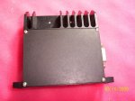
It looks like one of those heads with an internal calibration amplifier...
The identified end looks like you hook up a DMM or scope to the [GND]
and [+] terminals and adjust the 2 pots for [Offset] and [Gain] after
it is powered up.
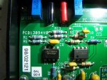
If you have a part # or Manufacturer... you might try to contact them...
Other than someone here having the same type of head that knows the
pinouts... you could trace down the pins to where they connect on the
electronics in the head..
Jerry
The identified end looks like you hook up a DMM or scope to the [GND]
and [+] terminals and adjust the 2 pots for [Offset] and [Gain] after
it is powered up.
If you have a part # or Manufacturer... you might try to contact them...
Other than someone here having the same type of head that knows the
pinouts... you could trace down the pins to where they connect on the
electronics in the head..
Jerry
- Joined
- Sep 20, 2008
- Messages
- 17,622
- Points
- 113
Like I said... you can trace the pins to the electronics inside to give you an
idea of where to connect (if you have some basic electronic skills that is)..
There should be 2 lines for the calibrated sensor output and 2 lines for power
to the electronics at least... maybe even a common ground..
Have you tried to Google the name...
Jerry
idea of where to connect (if you have some basic electronic skills that is)..
There should be 2 lines for the calibrated sensor output and 2 lines for power
to the electronics at least... maybe even a common ground..
Have you tried to Google the name...
Jerry
yes, for a month, and I'm doing that right now also... Thanks for the info, I am not familiar with this kind of meter, so I have no idea what I am looking for, I see there are opamps in it, but to tell you the truth, I dont know what they are doing with them. I had hoped someone knew something about this particular unit...
Attachments
Last edited:
- Joined
- Sep 20, 2008
- Messages
- 17,622
- Points
- 113
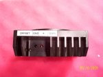
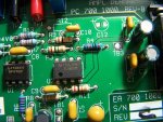
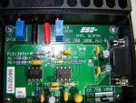
On your 3rd pic named "sens3.jpg" look at the 8 pin chip on the right...
It is a TL082CP op amp..
The top left most pin (#8) is connected to the Positive of the Supply and the
bottom right most (#4) is connected the Negative of the Supply.
The TL082CP IC uses a split supply at a maximum input voltage of +-18 Volts
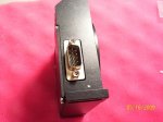
according to the spec sheet.. ( [+] [ground] [-] )
You should be able to trace those 2 pins to at least 2 of the pins of
the 9 pin "D" connector...
The test point to the right of this IC named TB3 is probably ground.. it should
also trace to a pin on the 9 pin connector..
The output of that IC (of the head) could be pin#1 the bottom left most pin
OR
pin#7 the top pin next to pin #8.. one of these two pins should go to the
9 pin "D" connector as the output to the LPM...
I am only guessing by what I see on the photos... but it would be the way
I would start to hunt down the connections...
Sorry I can't be of more help...
Here's the data sheet for the TL082CP....
http://www.datasheetcatalog.org/datasheet/SGSThomsonMicroelectronics/mXuxuyv.pdf
Jerry
It is a TL082CP op amp..
The top left most pin (#8) is connected to the Positive of the Supply and the
bottom right most (#4) is connected the Negative of the Supply.
The TL082CP IC uses a split supply at a maximum input voltage of +-18 Volts
according to the spec sheet.. ( [+] [ground] [-] )
You should be able to trace those 2 pins to at least 2 of the pins of
the 9 pin "D" connector...
The test point to the right of this IC named TB3 is probably ground.. it should
also trace to a pin on the 9 pin connector..
The output of that IC (of the head) could be pin#1 the bottom left most pin
OR
pin#7 the top pin next to pin #8.. one of these two pins should go to the
9 pin "D" connector as the output to the LPM...
I am only guessing by what I see on the photos... but it would be the way
I would start to hunt down the connections...
Sorry I can't be of more help...
Here's the data sheet for the TL082CP....
http://www.datasheetcatalog.org/datasheet/SGSThomsonMicroelectronics/mXuxuyv.pdf
Jerry
If that guy is not you then you can ask him for the pinout.
http://cgi.ebay.com/ws/eBayISAPI.dll?ViewItem&ssPageName=STRK:MEWAX:IT&item=300315485749
http://cgi.ebay.com/ws/eBayISAPI.dll?ViewItem&ssPageName=STRK:MEWAX:IT&item=300315485749
