

- Joined
- Apr 28, 2009
- Messages
- 111
- Points
- 0
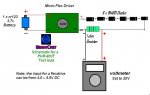
DIY Driver Test Load for PHR-803T Schematic
I have been asking questions all the time since im a LPF member but i wanted to aport something to the forum. So i tried to help aporting this schematic to how to read mA with a homemade test load .
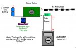
These schematics are for the purpose to regulate the mA of a Rkcstr or Flext-Drive Driver using a Voltmeter for then use it with a Phr-803T Diode.
You will need:
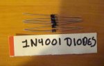
6 x 1N4001 Diodes
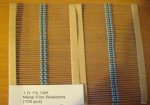
1 Ohm Resistor
Voltmeter
The Diodes and the resistor are connected in series.
Any error in these Schematics please post.
I have been asking questions all the time since im a LPF member but i wanted to aport something to the forum. So i tried to help aporting this schematic to how to read mA with a homemade test load .
These schematics are for the purpose to regulate the mA of a Rkcstr or Flext-Drive Driver using a Voltmeter for then use it with a Phr-803T Diode.
You will need:
6 x 1N4001 Diodes
1 Ohm Resistor
Voltmeter
The Diodes and the resistor are connected in series.
Any error in these Schematics please post.
Attachments
Last edited:


 A DMM typically has 3 1/2 digits, meaning the first digit only displays 0 and 1 (0.000...1.999). Note that this gives you the display resolution, it does not mean that the DMM is actually that precise! The "intrinsic" setting is the 200mV/200mA one; the others just use an internal resistor network to divide the input voltage/current by the appropriate power of 10, and shift the decimal point in the display.