Welcome to Laser Pointer Forums - discuss green laser pointers, blue laser pointers, and all types of lasers

LPF Donation via Stripe | LPF Donation - Other Methods

Links below open in new window

ArcticMyst Security by Avery

Driver I made is doing something odd...

Joined
Jan 20, 2008
Messages
1,724
Points
0
I've gone and made a driver using a LM1117 regulator from this schematic:
l1117.JPG

(Thanks to Phenol for the design!)

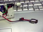
I have it set to 400mA using 4x 12.4ohm resistors off an old rkcstr driver, and it works well... Though, when you first turn it on it does this odd spike that really worries me... It starts off around 350mA, within a second it settles at 397mA, then just for a fraction of a second it jumps up to 510mA, then settles back down to 397mA where it stays for good.

This is a very consistent thing, it does it each and every time I turn it on... which worries me, since I'm not sure how well a LOC will handle 500+ mA spikes all the time...

The capacitors I'm using are 20v, 10uf tantalum surface mount ones... I've tried using a 47uf one on the output cap, but it doesn't seem to make a difference.
 

Attachments

  • Picture_008_002.jpg
    Picture_008_002.jpg
    39.7 KB · Views: 118


Joined
Sep 20, 2008
Messages
17,622
Points
113
What are you using as a load.... and how are you testing the current...
What is your 2.45V above the VLD voltage referenced to...

Jerry
 
Joined
Sep 20, 2008
Messages
17,622
Points
113
andythemechanic said:
I think the capacitor C2 is not needed. Maybe it causes intstabilities? Have you tried without it?


According to the Data Sheet the 10uF (C2) Capacitor is required for output stability
and can even be larger to attain that stability... :cool:

Jerry
 
Joined
Jan 20, 2008
Messages
1,724
Points
0
I've been using 4 big diodes in series, they say they're RL202... along with a 1ohm resistor. I'm measuring voltage across the resistor. I just found my rkcstr dummy load and tested with that, same results... It comes on, regulates, then jumps to 514mA, then drops back into regulation. Very odd.

I'm using a 12v wall wart for power, though I've tried with a partially dead 9v battery and saw the same behavior before it started dropping out of regulation.

Edit: I thought I'd take another pic of it, but it looks like you won't be able to make anything out using this camera..
 

Attachments

  • 2009-01-26-132403.jpg
    2009-01-26-132403.jpg
    124 KB · Views: 275
Joined
Sep 20, 2008
Messages
17,622
Points
113
pseudolobster said:
I've been using 4 big diodes in series, they say they're RL202... along with a 1ohm resistor. I'm measuring voltage across the resistor. I just found my rkcstr dummy load and tested with that, same results.

So far so good... have you read the Data Sheet... :-?
What is the reference to the 2.45Volt on the input... :-?

The data sheet "Typical Application" drawing for the LM1117 shows a 100uF on the input... maybe try that..  :cool:

The LM317 data sheet does in fact state and show a Current Regulated Application circuit...

But the LM1117 LDO does not mention this "Current Regulator application"... :-?

If the 100uF cap doesn't help stabilize the output... Just for a test...Try setting up the circuit
as a Voltage Regulator and see if the output stabilizes...

(here I'm just guessing)   ::)
It may be that because it is a Low Drop Out regulator... It may not fuction in the Current
regulator mode correctly....

Jerry
 
Joined
Jan 20, 2008
Messages
1,724
Points
0
Thanks for the help, lasersbee... I'm pretty sure the regulator is capable of being used for this purpose... It is after all, the same regulator used in the rkcstr driver, the groove driver, the fusion driver, and is fundamentally identical to the LM317T only that its dropout is a volt less.

I'm guessing you're on the right track though, that cap value is probably to blame here...
 
Joined
Jan 20, 2008
Messages
1,724
Points
0
lasersbee said:
What is the reference to the 2.45Volt on the input... :-?
That'd be the dropout... basically just a little memo that you'll need 2.45v on top of the laser's voltage...

lasersbee said:
The data sheet "Typical Application" drawing for the LM1117 shows a 100uF on the input... maybe try that..  :cool:
I'll try that, though I was under the impression the input cap would just be there to smooth out voltage spikes going to the driver... and if I'm using a 9v battery there shouldn't be any of those spikes... :-/
 
Joined
Aug 21, 2008
Messages
79
Points
0
In the LM117 reference paper i have it does show a 1A current regulator (page 17) but with only a 0.1uf cap on the input and no other caps on the output.

My guess about the spike would be that it's one of the caps reaching full charge causing the output to spike just before the regulator reacts to the increase and drops down to compensate.
 

L@z3r

0
Joined
Dec 24, 2008
Messages
217
Points
0
lol not to jack the thread but i noticed something funny about this picture
Maybe its just me
 

Attachments

  • ass_screws.jpg
    ass_screws.jpg
    69.6 KB · Views: 425
Joined
Sep 20, 2008
Messages
17,622
Points
113
Viracocha said:
In the LM117 reference paper i have it does show a 1A current regulator (page 17) but with only a 0.1uf cap on the input and no other caps on the output.

My guess about the spike would be that it's one of the caps reaching full charge causing the output to spike just before the regulator reacts to the increase and drops down to compensate.

Is that the LM117 you are quoting... :-? :-? :-?
Yes... it is similar to the LM317....

But the LM317 is not at all similar to the LM1117 which is the device being used...

Jerry
 
Joined
Sep 8, 2008
Messages
182
Points
0
lasersbee said:
[quote author=kernelpanic link=1233005189/0#11 date=1233015872]You are right. It's C2 causing a time lag in the response of the driver.  I'd remove C2 completely and use a smaller C3 (1 microFarad perhaps) Try it on a test load first of course. And always remember- Free advice is worth what you pay for it ;)

Cheers,
kernelpanic

As I've stated above.... the Data Sheet specifically states to use a 10uF cap or Larger on the Input..
There is a link to the Data Sheet on my last post... ::)

Jerry[/quote]

I wasn't suggesting altering the input cap. I was saying remove the sense cap and reduce the output cap. Scr*w the datasheet. Breadboard it then rip on me...

cheers,
kernelpanic
 
Joined
Sep 8, 2008
Messages
182
Points
0
Viracocha said:
In the LM117 reference paper i have it does show a 1A current regulator (page 17) but with only a 0.1uf cap on the input and no other caps on the output.

My guess about the spike would be that it's one of the caps reaching full charge causing the output to spike just before the regulator reacts to the increase and drops down to compensate.

You are right. It's C2 causing a time lag in the response of the driver.  I'd remove C2 completely and use a smaller C3 (1 microFarad perhaps) Try it on a test load first of course. And always remember- Free advice is worth what you pay for it ;)

Cheers,
kernelpanic
 
Joined
Sep 20, 2008
Messages
17,622
Points
113
pseudolobster said:
[quote author=lasersbee link=1233005189/0#5 date=1233009183]
What is the reference to the 2.45Volt on the input... :-?
That'd be the dropout... basically just a little memo that you'll need 2.45v on top of the laser's voltage...

lasersbee said:
The data sheet "Typical Application" drawing for the LM1117 shows a 100uF on the input... maybe try that..  :cool:
I'll try that, though I was under the impression the input cap would just be there to smooth out voltage spikes going to the driver... and if I'm using a 9v battery there shouldn't be any of those spikes... :-/
[/quote]
You are probably correct about using it as a current driver... if you say that other circuits use it that
way... (wish I had one in my hands... Then I could respond with more certainty...) ::)

The use of the 100uF cap on the input may be there to smooth out any intermittent regulator current
demands and not necessarily for Spikes.... Like when I'm designing Micro Controller Supplies... there is
always a 1uF Tant cap right across the Power Input to the MC.

BTW.... the Dropout Voltage of the LM1117 is typically 1.00 Volts not 2.45V as I read it on the Data Sheet...

http://pdf1.alldatasheet.com/datasheet-pdf/view/134370/ETC/LM1117.html

Jerry
 
Joined
Sep 20, 2008
Messages
17,622
Points
113
kernelpanic said:
You are right. It's C2 causing a time lag in the response of the driver.  I'd remove C2 completely and use a smaller C3 (1 microFarad perhaps) Try it on a test load first of course. And always remember- Free advice is worth what you pay for it ;)

Cheers,
kernelpanic

As I've stated above.... the Data Sheet specifically states to use a 10uF cap or Larger on the Input..
There is a link to the Data Sheet on my last post... ::)

Jerry


Top