hi, i'm new in this, so i need your help, the problem is this:
i watched a video on youtube, a phazons video i think.
I bought everything but not how i saw it:
1.- A Lm317T The video says Lm317
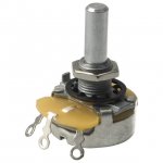
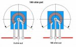
2.-A 500 ohms pot the video says a 25 ohm pot
3.- 2 res 10ohms the video says 2 res 10 ohms lol XD
4.- 1N4007 diode the video says 1N4001 diode
5.- 47mf 25 V capacitor The video says 47mf 35 V capacitor.
well. when i connected everything i used 2 batt. 1.5V each and i used a led of 3V, when i turn the pot the led lights perfectly. i did the same with a 6V led and 6 V of power.
Then, i soldered evrything, but when i powered it up...Nothing happened.
I changed the resistors, the LM317, the diode, the capacitor... and nothing happened.
I connect the multimeter in the end of the circuit ( Where the laser is sopossed to be) with the 6V batteries and when i connect the led,, the power lever decrease to 1.2 or 1.4.
I connected a power sorce of 6V and it still not work.
Does anybody knows why is this happening?
p.d srry about the gramatic, i'm new in this... and in the english too!! lol
i watched a video on youtube, a phazons video i think.
I bought everything but not how i saw it:
1.- A Lm317T The video says Lm317
2.-A 500 ohms pot the video says a 25 ohm pot
3.- 2 res 10ohms the video says 2 res 10 ohms lol XD
4.- 1N4007 diode the video says 1N4001 diode
5.- 47mf 25 V capacitor The video says 47mf 35 V capacitor.
well. when i connected everything i used 2 batt. 1.5V each and i used a led of 3V, when i turn the pot the led lights perfectly. i did the same with a 6V led and 6 V of power.
Then, i soldered evrything, but when i powered it up...Nothing happened.
I changed the resistors, the LM317, the diode, the capacitor... and nothing happened.
I connect the multimeter in the end of the circuit ( Where the laser is sopossed to be) with the 6V batteries and when i connect the led,, the power lever decrease to 1.2 or 1.4.
I connected a power sorce of 6V and it still not work.
Does anybody knows why is this happening?
p.d srry about the gramatic, i'm new in this... and in the english too!! lol