- Joined
- Feb 5, 2009
- Messages
- 114
- Points
- 18
Copper has better thermal conduction than aluminum, but aluminum is usually fine. What matters more than the type of metal is how good the connection is to the heat sink(press-fit, soldered, heat sink grease, etc.).
The numbers that you mention will not yield any useful information as far as we have been able to determine. The best thing to do is to examine/test them yourself. Here are a few guidelines:
-9mm can diodes are only CW in powers up to 2 watts.
-Generally, a bigger chip with more or bigger wires can take more power.
-From what we have discovered high power diodes are USUALLY case positive, red and IR both. If both are isolated from the case, the wire attached to the top of the die is negative.
-A great way to test the polarity is use the diode test function that is available on most multimeters.
-When trying to determine rated power the best thing to go off of is the threshold current at which it begins to lase. If you got them from Heruursciences/Hesc_photonics then they are LIKELY from Boston Laser. If you want I can post the specs from them because their site is gone. If they are from other sources I can't help you.
-Turn up the power of a good diode until it dies. Identical diodes should not be run at more than (very) roughly 2/3 of the power at failure.
-IR usually runs at 2.2v, red usually runs at 3v
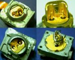
-The wavelength can sometimes be determined by the color tint of the front facet of the die. For example, if it is half green and half pink(lengthwise) then it is probably an 808nm diode. If it is purple, then it is probably a red diode.
Hope this helps!
The numbers that you mention will not yield any useful information as far as we have been able to determine. The best thing to do is to examine/test them yourself. Here are a few guidelines:
-9mm can diodes are only CW in powers up to 2 watts.
-Generally, a bigger chip with more or bigger wires can take more power.
-From what we have discovered high power diodes are USUALLY case positive, red and IR both. If both are isolated from the case, the wire attached to the top of the die is negative.
-A great way to test the polarity is use the diode test function that is available on most multimeters.
-When trying to determine rated power the best thing to go off of is the threshold current at which it begins to lase. If you got them from Heruursciences/Hesc_photonics then they are LIKELY from Boston Laser. If you want I can post the specs from them because their site is gone. If they are from other sources I can't help you.
-Turn up the power of a good diode until it dies. Identical diodes should not be run at more than (very) roughly 2/3 of the power at failure.
-IR usually runs at 2.2v, red usually runs at 3v
-The wavelength can sometimes be determined by the color tint of the front facet of the die. For example, if it is half green and half pink(lengthwise) then it is probably an 808nm diode. If it is purple, then it is probably a red diode.
Hope this helps!


")