Welcome to Laser Pointer Forums - discuss green laser pointers, blue laser pointers, and all types of lasers

LPF Donation via Stripe | LPF Donation - Other Methods

Links below open in new window

ArcticMyst Security by Avery

ddl circuit question

Joined
Oct 24, 2009
Messages
94
Points
0
so i have wondered why i have to connect potentiometers 2nd and 3rd pins together???

i measured that when you move potentiometer to rigth the resistance of rigth pin grows and left pin goes to less resistance so energy flows from left pin and when you move pot enough to left it changes and energy flows from rigth pin
so max resistance from pot should be less than sayed amount (example. if pot would be 100 ohm then max resistance of pot would be about 50 ohms) correct me if im wrong and why is 2 pins connected together?

:thanks:


HIMNL9

0
Joined
May 26, 2009
Messages
5,318
Points
0
This is usually made (at least, from when i play electronic, 35 years ago, i know it this way :p), cause if your potentiometer, for an accident, get the cursor broken, if you have connected just the center and one of the sides, you get an open circuit ..... instead, if the center pin is connected to one of the sides, if the cursor get broken, you end with the max value of the potentiometer, but not an open circuit .....

That was originally used, as far as i remember, from the old times of big industrial DC motors controllers with current loop feedback (what's called in English ? ..... case feedback ? ..... armor feedback ?), when, if you open the feedback loop, the motor go crazy and quickly start to rise the speed til it break itself (and who is around, if it's big enough ..... here we call this out-of-control rush "escape condition", but don't know the exact English translation, sorry)

Now DC controllers are much more perfectioned and don't cause this problem (if you don't intentionally take away excitation loop with the motor spinning at high speed, ofcourse :p), but probably the use to connect potentiometers in this way, when used as variable resistors, is remained for prevent open circuits .....

Just a personal opinion ;)
 
Joined
Oct 24, 2009
Messages
94
Points
0
so i have to connect those two pins to minimize the risk of dead diode?
 

HIMNL9

0
Joined
May 26, 2009
Messages
5,318
Points
0
Uhm, no, to avoid the risk to end with an open circuit ..... but thinking about it, anyway, if the driver (LM317 based) feedback circuit go open, the diode just receive 1,25V at insignificant current, so, no, i don't think it burn the diode ..... it's just a good use, all here.

If instead you're using a boost switching driver, then the thing can be different, and an open circuit can also turn the driver at max, instead turn it off, but this depend from the configuration of the driver ..... anyway, you're speaking about a linear driver with an LM317 and no other, if i've understood correctly.


Edit: and no, the pot don't change its max value, connecting the central to one side ;)
 
Joined
Oct 24, 2009
Messages
94
Points
0
how do i measure wich is central pin on pot (i have a multimeter)
 

HIMNL9

0
Joined
May 26, 2009
Messages
5,318
Points
0
Sorry, what do you mean, exactly ? :confused: 
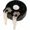
..... central (cursor) pin is in center, usually .....

Or do you mean in trimmers that have the pins placed in different non-standard configuration, like the old circular sealed ones that have the pins coming out from the sealed bottom in equilateral triangular shape ? ..... in this case, if you put, as example, an 100 ohm pot at middle position, then the two sided are where you measure the full 100 ohm, and from any of the 2 sides to the central, you measure half of the value (in case of logarithmic pot, the value is not half, but is ininfluent for identify the cursor pin, cause from this to any of the sides, you still measure less than the full value, when it's in the middle position)
 

Attachments

  • pot pins 01.jpg
    pot pins 01.jpg
    14.1 KB · Views: 2,245
  • pot pins 02.jpg
    pot pins 02.jpg
    22.2 KB · Views: 299
Joined
Oct 24, 2009
Messages
94
Points
0
yes its a trimmer.
so do i have to connect two pins wich are in same side?
 

HIMNL9

0
Joined
May 26, 2009
Messages
5,318
Points
0
uhm, can you post a pic of your trimmer ?

So, maybe, is more easy to understand what type of trimmer is, and reply you correctly.
 
Joined
Oct 24, 2009
Messages
94
Points
0
88e1ce9d5ac30c1118d0bd47e232d8c2.jpg

well thats not extact same but just 50 ohm difference
 

HIMNL9

0
Joined
May 26, 2009
Messages
5,318
Points
0
:crackup:

Well, sorry, but what other i can say ? ..... :p :D


@ GeGGuli: with this trimmer, the central (cursor) pin is the one that is alone, on the other side respect the two that you see in the pic (usually in these trimmers it's coming from a metallic ring at bottom of the trimmer).

attachment.php


You need to connect that with one of the 2 that you see in the pic (usually, as in your pic, is connected with the right one, so turning the cursor from left to right, the value decrease and the current increase)

If you use it in a linear driver, don't forget to put a fixed resistor in serie with the trimmer, for set the maximum current, and for limit the risk to burn the trimmer (as example, assuming that you're using an LM317 based driver, if you want to have a maximum current of 320mA, connect in serie with the trimmer a resistor of 3,9 ohm)
 

Attachments

  • trimmer.jpg
    trimmer.jpg
    56.7 KB · Views: 1,538


Top