Welcome to Laser Pointer Forums - discuss green laser pointers, blue laser pointers, and all types of lasers

LPF Donation via Stripe | LPF Donation - Other Methods

Links below open in new window

ArcticMyst Security by Avery

Buildind my first DDL Driver

Joined
Mar 7, 2010
Messages
123
Points
18
Hey guys am trying to build my first driver..i id some reading on them and i would just like someone to help me confirm that these are the right pats to use, thank you..

LM317

Variable 100 omh resistor

1N4001 Diode

10mf 16v Capacitor
Im not sure if this surfae mount is the best...

And well as for the 10ohm Resistors i have two of those from radioshake already..im from trinidad thats why i choose ebay, if anyone has advice on buying this from somewhere else please let me know...


Joined
Mar 17, 2010
Messages
217
Points
0
Yes, these are the right parts to use. However the resistor you need is determined by a formula: R = 1.25 / desired_current_in_A. So it depends on what current you want. For example: for 400mA, you would need 1.25/0.4 = 3.125 ohms.
 

jaycey

0
Joined
Apr 10, 2009
Messages
480
Points
18
Unless you have experience in smd components and have to have small build then go for a standard radial electrolytic type capacitor, save yourself some trouble!

Good luck
 
Joined
Aug 28, 2009
Messages
1,071
Points
0
Unless you have experience in smd components and have to have small build then go for a standard radial electrolytic type capacitor, save yourself some trouble!

Good luck
Without the right tools and equipment, SM is a real pain in the @ss.
As jaycey stated, go with the standard PCB thru-hole components.
 
Joined
Mar 7, 2010
Messages
123
Points
18
Yes, these are the right parts to use. However the resistor you need is determined by a formula: R = 1.25 / desired_current_in_A. So it depends on what current you want. For example: for 400mA, you would need 1.25/0.4 = 3.125 ohms.

Thank you for your reply, but i dont quite understand what you mean...is this the variable resistor you are talking about? can you please explain this to me again...sorry to me subborn...

Unless you have experience in smd components and have to have small build then go for a standard radial electrolytic type capacitor, save yourself some trouble!

Good luck
Thank you for your reply, i know smd components are stress to deal with but the thing is thats all i could fid on ebay that would ship to trinidad..can you point me to another seller that would ship to me?

Without the right tools and equipment, SM is a real pain in the @ss.
As jaycey stated, go with the standard PCB thru-hole components.

Thank you for your reply, do you know where i can get it?
 

jaycey

0
Joined
Apr 10, 2009
Messages
480
Points
18
Your variable resistor is fine, the 10ohm resistors you allready have is whats determins your MAX output (mah) so you vary this resistor to suit your diode.

EXAMPLE: 1 x 10ohm resistor will give you a max output of 125mah which is good for a PHR 803t bluray diode (although they have been known to die at this output) 80-90mah is safe.

So if you have maybe a LOC Red this will need a safe output of around 400mah, to get this you will need a resistor around 3ohm, probably giving you a max of around 500mah (cant do the exact maths right now!)


The capicitor value is not critical, you need to have a voltage value of at least twice your input power, so if you are using a 9v power supply, go for at least an 18v capicitor etc...
 
Joined
Mar 7, 2010
Messages
123
Points
18
Your variable resistor is fine, the 10ohm resistors you allready have is whats determins your MAX output (mah) so you vary this resistor to suit your diode.

EXAMPLE: 1 x 10ohm resistor will give you a max output of 125mah which is good for a PHR 803t bluray diode (although they have been known to die at this output) 80-90mah is safe.

So if you have maybe a LOC Red this will need a safe output of around 400mah, to get this you will need a resistor around 3ohm, probably giving you a max of around 500mah (cant do the exact maths right now!)


The capicitor value is not critical, you need to have a voltage value of at least twice your input power, so if you are using a 9v power supply, go for at least an 18v capicitor etc...

Thank you! i totally understand now, but i would be using a digital multimeter to set my output, so i was planning on letting the total output be as high as i can get it so that i would be able to have a greater range on settings using the same driver...is this a good idea or not? thanks for the advice..
 

jaycey

0
Joined
Apr 10, 2009
Messages
480
Points
18
No harm in doing that, make sure you use a test load when you set your current.

The only difference being that your pot will get more sensitive as you increase the max potential output.
 
Joined
Feb 5, 2008
Messages
6,252
Points
83
You should forget the potentiometer,
and simply use one fixed resistor to set one current to run your laser at.

No point in havinga pot, you will simply overshoot the current and kill your laser diode.
X-zek explained nicely in #2 post.

If someone told me I don't need the damn potentiometer, I would not have around 30 red laser diodes body count.
 
Joined
Mar 7, 2010
Messages
123
Points
18
No harm in doing that, make sure you use a test load when you set your current.

The only difference being that your pot will get more sensitive as you increase the max potential output.

Thanks for the advice, can you please explain why i need a test load and what i should use? Thanks..

You should forget the potentiometer,
and simply use one fixed resistor to set one current to run your laser at.

No point in havinga pot, you will simply overshoot the current and kill your laser diode.
X-zek explained nicely in #2 post.

If someone told me I don't need the damn potentiometer, I would not have around 30 red laser diodes body count.

Do you have a diagram of this circuit without the pot? can you send me a link? thank you..
 

jaycey

0
Joined
Apr 10, 2009
Messages
480
Points
18
A test load simulates having a laser diode attached to your driver to enable you to accurately set your output current.

For a red diode you use 4 1N40001 diodes for a bluray 6 1N4001 diodes & a 1ohm resistor.

Heres a diagram
test%20load01.jpg


You only need to use a test load & measure your output if you are going to use the circuit with a variable resistor (pot)

Thanks to our old friend Rog for the diagram.
 
Joined
Feb 5, 2008
Messages
6,252
Points
83
Joined
Mar 7, 2010
Messages
123
Points
18
Guys you are totally awesome!! I love this forum :thanks:
So i decided to go with the driver without the pot since i have a good feeling i would turn the pot to high and blow my diode..
I went out today to look for the parts and these are all i can find..
LM317
1N4003......I know its suppose to be 1N4001 but the girl there said that its the same, can anyone tell me if this is true?
3.3 1/2watt resistor........Whats the purpose of 1 Watt or half Watt?
Im using an open can red laser, so with 3.3 resistor i shoud get about 378mA output, that should be good right? please give me any advice that you all think i might need, and thanks again..
 

jaycey

0
Joined
Apr 10, 2009
Messages
480
Points
18
Lets not show someone how to "run before they can walk"

My driver was large to illustrate to people who have not put one together before how it "can" be done.

I dont think someone new to electronics is going to grab a handfull of SMD components and put together one of those.

Nice little driver btw


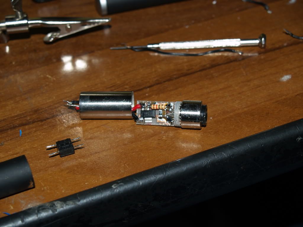
That is quite large, try this:

PA234913.jpg


It is LM1117 chip, everything is exactly the same except that Vdrop of the IC is only half of 317.
What you are seeing here is a driver used is my first bluray pen build, run off 2x 10440.


Top