Welcome to Laser Pointer Forums - discuss green laser pointers, blue laser pointers, and all types of lasers

LPF Donation via Stripe | LPF Donation - Other Methods

Links below open in new window

ArcticMyst Security by Avery

Blank Battery Contact Board connection

Joined
May 9, 2013
Messages
838
Points
43
I'm having some trouble with getting power - to my brain apparently. I ordered a drilled pill/brass ring and battery contact board from Survival Laser to complete my very first build... well, more assembly (this host) than build since I ordered the driver preset and diode already in module from DTR. At any rate, not wanting to solder the driver leads on yet for fear my n00ba$$ would damage something, I thought I could place the battery board into brass ring and then ring into pill... assemble in lower part of host with battery and tail cap switch all together, then measure voltage across the leads from the battery contact board to verify I was getting proper battery power to what would soon be soldered to the driver input.

Well, apparently not all the bulbs on my tree are functioning. I get no voltage across the contact board leads.
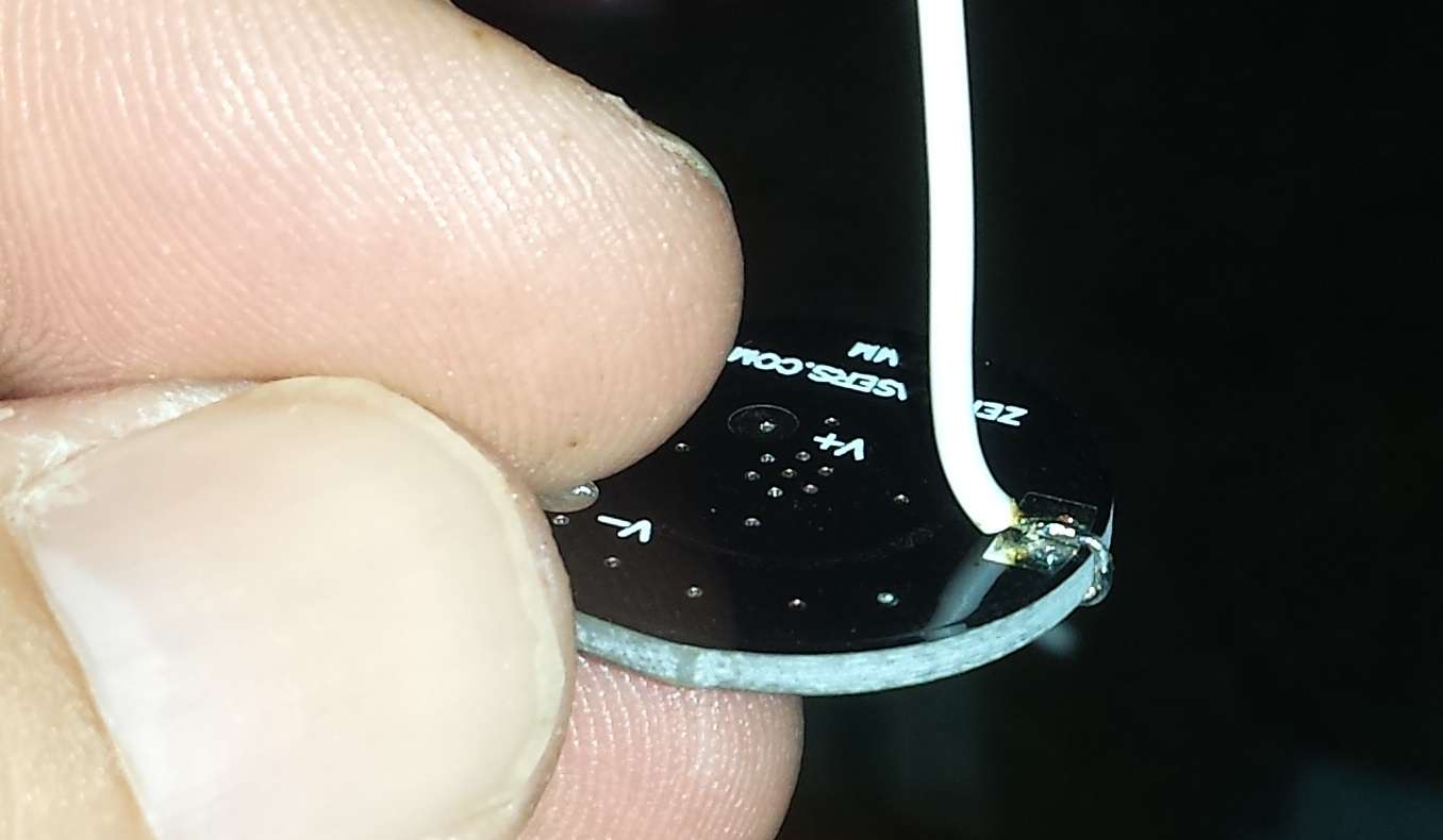
I've verified the tail switch is working by measuring resistance across switch with multimeter (toggling) and the 18650 is charged, so no issue there, but when I disassemble it all again and check the board, I get high resistance from any surface on the lower part of the contact board (ie. outer ring or center "circle") to either lead on the board.

I guess I just don't get how this is supposed to work...
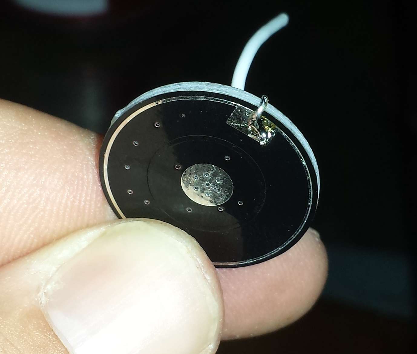
I thought the host carried the negative connection and this was completed by the battery contact board contact to the brass ring (which I placed a tiny dab of solder on the outer ring of the board to connect it to the brass ring), brass ring to pill, and pill to host, so if everything had good contact, why wouldn't I see a voltage across the leads on the blank battery circuit board? I used a small metal washer on negative side of battery in host to make contact since only the tailcap end has a spring and I'm using a flat top. I'm pretty sure contact was made.

I would appreciate any words of wisdom.

Thanks!!
c

ps. the dab of solder idea was just a shot in the dark after seeing Survival Lasers pic of the battery side of the board here... it was the last thing I tried before giving up and posting here


DTR

0
Joined
Jun 24, 2010
Messages
5,684
Points
113
Could be the solder blob you are trying to use. I prefer to get the negative lead from the underside so that the board presses it against the wall of the pill. Like this. It is much more secure than trying to solder to brass or aluminum. This is a different board but the idea is the same.:beer:

d1q4.jpg


y753.jpg
 
Last edited:
Joined
Dec 29, 2009
Messages
3,136
Points
63
what batteries, button tops? If flat tops, you need a spring on the + battery pad on the contact board, I'd reckon.

but when I disassemble it all again and check the board, I get high resistance from any surface on the lower part of the contact board (ie. outer ring or center "circle") to either lead on the board.

Do you mean that the pads that touch the battery + and the battery - (i.e. outer ring on board) are NOT continuous with anything on the topside of the board? This would indicate a problem... Got pics of your contact board? Is it exactly this one: http://d13z1xw8270sfc.cloudfront.net/origin/180261/blank_contact_board.jpg

If so, red wire should be continuous with center pad on the back, and black wire continuous with outer ring on both sides.
 
Joined
May 9, 2013
Messages
838
Points
43
I was under the impression the red wire was continuous with the center pad on back and the black wire continuous with outer ring on back without me soldering a wire through the board to make that happen... maybe that's where I'm dropping the ball. In looking at the pics above, it's pretty clear I need to bridge that connection myself. I just misunderstood that was already part of the contact boards connections when the wires were soldered on.

I really am new to this... I haven't ventured into any sort of electronics or electrical project since I was a kid... so there are layers of rust that need to be knocked off. I appreciate the help.


If so, red wire should be continuous with center pad on the back, and black wire continuous with outer ring on both sides.
 
Joined
Dec 29, 2009
Messages
3,136
Points
63
No, no, what you thought is what I was trying to say. The pic above, by DTR, is just his own, successful, way of creating an interference fit contact, rather than soldering to the brass ring. I apologize for not explaining properly. Also, sorry in advance, because I have a feeling that in trying to clarify what I said, I will just confuse folks further.

By the quote you quoted from me, that is how the board should be right now, as received from the shop. You should be able to probe red wire and the center pad and get no resistance, and you should be able to probe black wire and outer ring and get no resistance.

Should be you solder outer ring to brass ring, screw brass ring into host, and that makes the outer ring on the contact board (and by association, the black wire) at the same electric potential as the host (usually negative on a negative-switched design)
 
Last edited:
Joined
May 9, 2013
Messages
838
Points
43
Ok, well it's not like that now... I can probe the red wire and center ring and/or black wire to outer ring and there is massive resistance either way (OL on anything but megaohm scale). So, apparently I need to bridge those connections with a wire.

Thanks for your patience. I just misunderstood how it came... as long as I know what to do, it's ok. Maybe it was supposed to be like that, but this one came without the connections to the bottom (battery facing) pads.

Thanks so much again!
c
 
Joined
Dec 29, 2009
Messages
3,136
Points
63
I'd see if you can find some other pads on the topside that ARE continuous with the + and - on the battery side using a multimeter, and either move the existing leads to those pads, or bridge the correct pads to the pads the wires are soldered to using a very small length of wire (or even a solder blob, if you can beat the surface tension).

Just as a test, you can touch the two multimeter leads together and get ~ 0 ohms, right? Because sometimes the 250mA fuse on the low current side blows but the meter doesn't tell you this.
 
Joined
May 9, 2013
Messages
838
Points
43
Yeah, my Fluke is working fine. I test it regularly on known sources and check resistance by shorting leads before checking something else.

I just drilled a tiny hole at the edge of the board and another near the center and jumpered some wire through to each area. I left as much of the wire as I could in the shielding to try and minimize the chance of unsavory touching. For the center section, I had a small washer I was going to use in lieu of a spring to raise it enough to make contact with the flat top 18650, but I couldn't get a successful hold due to my shoddy soldering skills, so I just made a blob of solder instead. I assembled the bottom half of the host and tested the voltage across the leads going to the driver and everything checked out, so I soldered the driver leads in and finished the assembly.

The result - my very first build... a 200mW 450nm. The flash went off while I was trying to take a photo of the beam with my iPhone. I kinda like the way it knocked a lot of the highlight out of the beam and gives that blue blue color. Anyhoo, thanks for the help!

r5dg.jpg


Top