Welcome to Laser Pointer Forums - discuss green laser pointers, blue laser pointers, and all types of lasers

LPF Donation via Stripe | LPF Donation - Other Methods

Links below open in new window

ArcticMyst Security by Avery

2 diodes, both dim? (Now w/ Pics)

Joined
Jan 13, 2008
Messages
16
Points
0
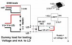
do you have a good picture of this test you are talking about? I want to make sure I do it correct.
So, I would be removing the LD and not having it connected during the load test?
What about the resistors, diode and cap in the circuit? Are they used during the load test?


Joined
Jul 24, 2007
Messages
2,749
Points
0
I have posted the test procedure from another thread:-
Things to check before you start testing

1) Is it wired correctly?

2) Is there enough voltage? (Rule of thumb 6v for reds 9v for blue)

3) If supply is via batteries, are they fresh? (Used ones may sag and effect your measurements)

Now to test it out......

4) Attach the 4 diodes and resistor to where LD will eventually connect. If your reverse diode and capacitor are already connected to your LD you can connect your test assembly to the output from your fixed resistor and the neg of the battery.

5) Turn the pot to maximum resistance (then back off the pot a turn if it is a 25 turn one to ensure the wiper is not right on the end of the resistor track)

6) With your DVM set to volts attach red and black leads as shown at either end of the diodes. Turn on supply, now wind your pot right up to see if the voltage doesn't exceed your required voltage.

7) Turn off the supply, change range on DVM to mv and attach red and black as shown either end of resistor. Turn on supply and the mv reading will be equal to the maximum milliamps that your LD would see, now wind the pot resistance up to check that the reading reduces smoothly down to the lowest mw, which equals the lowest ma your LD will see.

8) You can also connect your DVM, set to volts across the Vout and Vadj pins of the regulator, you should read 1.25v (thanks rckstr)

9) If all seems OK leave the pot at max resistance, disconnect the supply and remove your test assembly.

10) VERY IMPORTANT! If your capacitor is not connected directly to your diode (in other words it is already in the circuit with your regulator) you MUST short out the + and - at the output with a piece of wire to discharge the capacitor. Failure to do so will blow your LD as you connect it up!

The rest of the set up is up to you, the above only checks that the circuit works correctly.

The figures you gave earlier in this thread suggest to me that the circuit is doing the right things, if the LD's are blown I am surprised that you get a dot at all, as I understand it they usually end up with an LED, you seem to still have a laser :-/....... I would say that I have never fried a red so I do not speak from experience, maybe someone else can confirm.

Regards rog8811
 

Attachments

  • DDL_circuit_test01.jpg
    DDL_circuit_test01.jpg
    99.1 KB · Views: 191

Gazoo

0
Joined
Jun 9, 2007
Messages
3,206
Points
38
I have seen at least 15 dots like that from diodes that suffered from COD. They were then sent to their proper resting place and given their last rites.. ;D

It is a good idea to keep them...you can use them as a load for testing. A diode that has suffered from COD will draw the same amount of current as a good diode. But it will get noticeably hotter.
 
Joined
Oct 28, 2007
Messages
2,631
Points
48
as you can see from my signature thing below this message, I have killed a bunch of these suckers. when these babies die, you can focus them to some extent, but when focused, you get a dim dot with a line through it, it looks just like the dot on his 12ft away pic.

so yes its dead, and yes you can keep it as a test, or "dummy" load.

you keep the capacitors and everything in the circuit!

pretend like the 4 IN4001's are just a laser diode. they are your "load". connect them to your driver output jsut liek you would a laser diode, except this time connect your DMM in series, meaning the + probe on the DMM goes to the + output on your driver,
the - probe on your DMM goes to the + end of your IN4001 setup.

set your DMM to the 10A setting (or the highest range DC current you have),make sure the probes are connected to the right ports on your DMM, turn your driver on, and you will get a correct current reading.

regards,

amk
 
Joined
Jan 13, 2008
Messages
16
Points
0
I'll, attempt this soon. I have college classes bombarding me right, so maybe this weekend.

If I can keep the LD as a dummy load then do I still need to use the 4 diodes as a load? Or will the dead LD work as the load?

Also, seeing as I now have no more LD's, where is a good place to get some more? I used e-bay and it took for ever to get them.

Oh, and can someone tell me exactly why 3 LD's died? I'm still not sure what happen.
 

Gazoo

0
Joined
Jun 9, 2007
Messages
3,206
Points
38
The LD is all you need for the load.

The biggest cause of killing diodes is from measuring current between the diode and the capacitor. What happens is many people hook up their meter to the circuit with the power turned on. This causes a killer spike because the diode is getting the full voltage from the regulator and capacitor, which is more than 5 volts. The best way to prevent this is to measure between the power source and the circuit.

You can get more diodes here:

http://sales.stonetek.org/
 
Joined
Oct 28, 2007
Messages
2,631
Points
48
LOL someone modified my post, and made the capacitors and everything part big...

too bad it doesnt say "post edited" anymore...

regards,

amk


Top