-----------------Notes on the size of images - I don't know how to have the images come up full size automatically, but double-clicking will get them big enough to see.-------------------
I watched Star Trek from the 1st episode onward, through all the series iterations, and as far as enthusiasm goes, I am a ‘Trekie’.
A couple months back I saw a YouTube video of Arctic Lasers 1 Watt blue laser. That really got my interest up, and I then happened on to LaserPointerForums, where I started reading. And the reading was very valuable, as I really did not understand the potential dangers. So thanks to all for that education.
And then I saw JayRob’s Playmates Phaser build How-To ---- I just HAD to have one, so I started ordering parts. I wanted a GREEN laser, for easy astronomical use – after all, when you’ve spotted UFOs (Klingons?) using your Gen3 Night Vision Goggles, you need to be able to point them out to others!
Because this was to be my first ever laser build, I opted for the lowest (50mW) green o-like module that JayRob recommended.
I wanted to use both the safety switch & the ‘snap-action’ trigger switch, but their contact ratings were only 100mA – using them to drive the o-like module would be way beyond their design range. I looked for and found a very small 3-Volt relay with contacts rated for 1Amp. So I got two on order. Along with switches, diodes, LEDs, etc.
I ordered a copper heat-sink (future upgrades in power?) from JayRob, and had him install his light-pipe in the ‘Stun/Kill’ rotary switch, and drill out the plastic nose-cone.
Before going too much further I drew out the wiring for the original Phaser, then planned out the changes I wanted to make. The changes retain the same functioning as JayRob’s version – sound only with safety switch in off position (green LED safety indicator off), and sound, green LED safety indicator on, AND Laser module enabled with safety switch ON. The colors for the wires on the un-modified Phaser are what you should see when you open up your Phaser. The colors called out for the modifications are the result of cutting up an old printer cable and using what was available. The 2 schematics are the before & after wiring.
View attachment PHASER_orig.pdfView attachment PHASER_modified.pdf
Photo 1 is the original sound board, with the domed trigger switch removed. The yellow wire goes to the center contact of the Stun/Kill slide switch. The 2 gray wires go to the variable resistor used to control brightness on the original. The orange wire goes to one side of the light bulb in the original. The hidden brown wire goes to the other side of the light bulb.
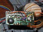
I will not be using the variable resistor, so the gray wires will be removed. The orange wire will be removed, as the o-like module will be getting its power from one of the new relays. The yellow wire will be removed from the sound board, and get fed from the new trigger switch.
I elected to run a ground wire directly from the battery compartment to the o-like module, so I removed the brown wire that could have been used for that purpose. I then moved the black wire (main ground for the sound board) inboard to where the brown wire was, as removing/relocating all these wires gives me more room to seat the new trigger switch.
Photo 2 shows the 2 gray wires and the orange wire removed. The brown & black wires are now visible along the top edge of the board – this is before removing the brown, and relocating the black. The yellow wire will be removed later and wired as per the modified schematic.
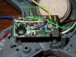
The LED I used for the safety indicator was an ultra-bright. Putting a 47ohm resistor in series limited current to approx 4-1/2 mA and was easily visible in the daylight and doesn’t seem too bright at night. NOTE: after getting everything completed, I think it is TOO BRIGHT at night.
In mounting the LED into the switch, I used a Dremel tool thin saw to cut 2 slots to feed the LED leads out of the plastic. This also helped to mechanically hold the LED in position. Photo 3 shows the position of the saw, and Photo 4 shows the LED in position in the switch. The resistor in soldered in line where it doesn’t cause a bind when the switch is rotated.
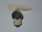
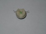
Photo 5 shows the very small 3-volt relays with a steel scale for reference.
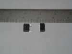
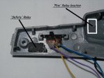
Photo 6 shows one of the relays dropped into its final resting place, before any wires were attached.
I just reached my upload file limit, so I will start a continuation thread that has the remainder.
Cheers,
Steve
I watched Star Trek from the 1st episode onward, through all the series iterations, and as far as enthusiasm goes, I am a ‘Trekie’.
A couple months back I saw a YouTube video of Arctic Lasers 1 Watt blue laser. That really got my interest up, and I then happened on to LaserPointerForums, where I started reading. And the reading was very valuable, as I really did not understand the potential dangers. So thanks to all for that education.
And then I saw JayRob’s Playmates Phaser build How-To ---- I just HAD to have one, so I started ordering parts. I wanted a GREEN laser, for easy astronomical use – after all, when you’ve spotted UFOs (Klingons?) using your Gen3 Night Vision Goggles, you need to be able to point them out to others!
Because this was to be my first ever laser build, I opted for the lowest (50mW) green o-like module that JayRob recommended.
I wanted to use both the safety switch & the ‘snap-action’ trigger switch, but their contact ratings were only 100mA – using them to drive the o-like module would be way beyond their design range. I looked for and found a very small 3-Volt relay with contacts rated for 1Amp. So I got two on order. Along with switches, diodes, LEDs, etc.
I ordered a copper heat-sink (future upgrades in power?) from JayRob, and had him install his light-pipe in the ‘Stun/Kill’ rotary switch, and drill out the plastic nose-cone.
Before going too much further I drew out the wiring for the original Phaser, then planned out the changes I wanted to make. The changes retain the same functioning as JayRob’s version – sound only with safety switch in off position (green LED safety indicator off), and sound, green LED safety indicator on, AND Laser module enabled with safety switch ON. The colors for the wires on the un-modified Phaser are what you should see when you open up your Phaser. The colors called out for the modifications are the result of cutting up an old printer cable and using what was available. The 2 schematics are the before & after wiring.
View attachment PHASER_orig.pdfView attachment PHASER_modified.pdf
Photo 1 is the original sound board, with the domed trigger switch removed. The yellow wire goes to the center contact of the Stun/Kill slide switch. The 2 gray wires go to the variable resistor used to control brightness on the original. The orange wire goes to one side of the light bulb in the original. The hidden brown wire goes to the other side of the light bulb.

I will not be using the variable resistor, so the gray wires will be removed. The orange wire will be removed, as the o-like module will be getting its power from one of the new relays. The yellow wire will be removed from the sound board, and get fed from the new trigger switch.
I elected to run a ground wire directly from the battery compartment to the o-like module, so I removed the brown wire that could have been used for that purpose. I then moved the black wire (main ground for the sound board) inboard to where the brown wire was, as removing/relocating all these wires gives me more room to seat the new trigger switch.
Photo 2 shows the 2 gray wires and the orange wire removed. The brown & black wires are now visible along the top edge of the board – this is before removing the brown, and relocating the black. The yellow wire will be removed later and wired as per the modified schematic.

The LED I used for the safety indicator was an ultra-bright. Putting a 47ohm resistor in series limited current to approx 4-1/2 mA and was easily visible in the daylight and doesn’t seem too bright at night. NOTE: after getting everything completed, I think it is TOO BRIGHT at night.
In mounting the LED into the switch, I used a Dremel tool thin saw to cut 2 slots to feed the LED leads out of the plastic. This also helped to mechanically hold the LED in position. Photo 3 shows the position of the saw, and Photo 4 shows the LED in position in the switch. The resistor in soldered in line where it doesn’t cause a bind when the switch is rotated.


Photo 5 shows the very small 3-volt relays with a steel scale for reference.

Photo 6 shows one of the relays dropped into its final resting place, before any wires were attached.

I just reached my upload file limit, so I will start a continuation thread that has the remainder.
Cheers,
Steve


