LPF Donation via Stripe | LPF Donation - Other Methods
Links below open in new window
ArcticMyst Security by Avery


You are using an out of date browser. It may not display this or other websites correctly.
You should upgrade or use an alternative browser.
You should upgrade or use an alternative browser.
Schematics for an SLD1239JL-54 driver please
- Thread starter redelman
- Start date


jayrob
0
- Joined
- Sep 21, 2007
- Messages
- 9,862
- Points
- 113
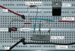
Here's the diagram of a very popular driver that is commonly called the 'DDL driver'. (made famous by Daedal)
http://www.laserpointerforums.com/forums/YaBB.pl?num=1185701612
If you build it exactly like this diagram, it will give you adjustable current from about 11mA's to 125mA's.
But if you want more power, replace the 10 ohm resistor with a 3 ohm resistor, and the adjustment becomes 12mA's to about 420mA's.
Using the Sony/Senkat diode that you mentioned, your supply voltage should not drop below 6 volts. This is why you should use 2 X 3.6 volt batteries. It will do well for you at 250mA's (around 170mW's), or 300mA's (about 200mW's) with an AixiZ acrylic lens. If your going to push it to 200mW's, you should use a good size heatsink for the AixiZ module...
Also, when you test the driver, you must remember to short the leads to discharge the cap (47UF 16V), before you connect your LD. (the cap will hold a charge and would kill your LD)
Jay
Attachments
jayrob
0
- Joined
- Sep 21, 2007
- Messages
- 9,862
- Points
- 113
If you built it just like the picture, using a 10 ohm resistor, the max current you will get is 125mA's. This would probably only give you around 75 or 80mW's. The diode should be very safe at that low power. (which is still very hazardous and can damage the eye instantly with a direct shot)
The cap will still hold a charge when testing the driver though, so remember to short the leads before connecting the LD...
Jay
The cap will still hold a charge when testing the driver though, so remember to short the leads before connecting the LD...
Jay
jayrob
0
- Joined
- Sep 21, 2007
- Messages
- 9,862
- Points
- 113
That question is not in my language. ;D
But I can tell you that it is a 47UF 16V cap. There is a link to the driver thread from Daedal in the post where I showed the picture. It is probably the longest thread on this forum!
Jay
But I can tell you that it is a 47UF 16V cap. There is a link to the driver thread from Daedal in the post where I showed the picture. It is probably the longest thread on this forum!
Jay
jayrob
0
- Joined
- Sep 21, 2007
- Messages
- 9,862
- Points
- 113
Soldered to the middle, basically it's like just connecting those two legs together, and then soldering the wire that comes from the center leg of the LM317 on to it...
Jay
Jay
- Joined
- Oct 24, 2008
- Messages
- 1,057
- Points
- 48
redelman said:How many microfarauds is the capacitor? Also if I can't find an 100 ohm potentiometer could I use let's say a 90 ohm and add a 10 ohm resistor? If so what part of the potentiometer would I put the 10 ohm resistor?
Don't do this you wont get max output. The driver supplies more current the LOWER the resistance is across the LM317. So if you put that 10 ohm resistor in series with another resistor and the pot just to get 100 ohm your min resistance will be the sum of the two resistors. Using a 90 70 or even 50 ohm pot is fine for diodes that require high current. Threshold current wont be achieved until the resistance is in the neighbor hood of 50ohm (I think, someone correct me if I'm wrong).
Also since the diode uses only about 3v, 6v should be OK. But like Jay said don't let it fall too much or you wont have max output. I don't really like using obscure batteries.
Once you have finished making it test it on a mini incandescent lamp. When you first hook it up to your diode ground the cap and turn the pot all the way up (Max resistance). Then apply power and slowly turn it down until desired power level is reached.
Another thing I do when I use these circuits is to attach a mA meter in series with the diode and driver to see in real time how much current the diode is being run at. This will also prevent you form supplying the diode with too much current and ruining it. Good luck.
-Mark
Can I use this type of potentiometer? http://www.allelectronics.com/make-a-store/item/LPP-100/100-OHM-LINEAR-POT-PC-MOUNT/1.html
Also how do I know which pin on a regulator is vin and which is vout?
Also how do I know which pin on a regulator is vin and which is vout?
- Joined
- Oct 24, 2008
- Messages
- 1,057
- Points
- 48
redelman said:Can I use this type of potentiometer? http://www.allelectronics.com/make-a-store/item/LPP-100/100-OHM-LINEAR-POT-PC-MOUNT/1.html
Also how do I know which pin on a regulator is vin and which is vout?
Yes that will be fine, especial since it is a linear taper pot.
Refer to this:
http://bp2.blogger.com/_4wHo2MPDwAc/R2YuBFTq09I/AAAAAAAAAAU/4FCiHm71rQE/s1600-h/Driver
Also another thing, can I use a 47uF 35 volt electrolytic capacitor instead? If not, can I use a 47 uF 16V radial? Or can I use this http://www.newark.com/25M8467/passives/product.us0?sku=multicomp-cb1c476m2kcb Also, the picture of the circuit is a little confusing can anyone draw me schamatic instead? Thanks
- Joined
- Oct 24, 2008
- Messages
- 1,057
- Points
- 48
Any capacitor from 10uF to 47uF will be fine. The voltage rating on the capacitor is it's maximum voltage it can handle. Since the diode only uses about 2-3v you will be fine.
The schematic shows the hookup of the components in terms of a picture. The two resistors in a parrallel are not necessary one will do. Make that resistor like 5-10 ohms and the pot should be around a 100 ohms.
When you test it turn the resistance on the pot all the way up and slowly decrease the resistance until you reach the desired current or brightness. You may want to hook up a multi meter to measure the current. You want to aim for about 250-300mA. You can use a 6v source to power the unit.
Please ask if you have any more questions. I encourage others to correct me if I am wrong about something.")
-Mark
The schematic shows the hookup of the components in terms of a picture. The two resistors in a parrallel are not necessary one will do. Make that resistor like 5-10 ohms and the pot should be around a 100 ohms.
When you test it turn the resistance on the pot all the way up and slowly decrease the resistance until you reach the desired current or brightness. You may want to hook up a multi meter to measure the current. You want to aim for about 250-300mA. You can use a 6v source to power the unit.
Please ask if you have any more questions. I encourage others to correct me if I am wrong about something.
-Mark
Instead of that round potentiometer I mentioned, I got this kind instead. http://www.westfloridacomponents.co...P120&Category_Code=TrimmerPots&Store_Code=wfc notice in the picture that there are numbers labeled above the pins? Which number is the one that connects to the resistor and which number connects to the middle pin? Also which direction do I turn the pot to get maximum resistance. Sorry for asking so many questions but hopefully this will be my last one(if i don't run into any problems). Thanks
