Welcome to Laser Pointer Forums - discuss green laser pointers, blue laser pointers, and all types of lasers

LPF Donation via Stripe | LPF Donation - Other Methods

Links below open in new window

ArcticMyst Security by Avery

Red Laser Diode to Driver Question

Joined
May 26, 2015
Messages
10
Points
0
Hey!

I bought a TMART red 1mw laser pen and disassembled it to attach a stronger red diode which I took out of a DVD-RW drive to the original driver.

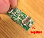
The driver has a spring on it if this is not well recognizable in the pics.
I tried all possible pin-to-driver positions but it still didn't work.
The diode still works (tested it with two triple A's).

The laser pen is powered by 2 AAA'S.

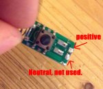
Do you know which pins from the diode belong to which position on the driver?

Or do you have any other solutions?

Kind Regards!


gozert

0
Joined
Nov 18, 2014
Messages
1,076
Points
63
You can't just solder a diode to any driver. It has to have the current adjusted to what's right for that specific diode. I would recommend finding out at what current your diode performs at it's best and then find a driver that suits your needs.
 
Joined
May 26, 2015
Messages
10
Points
0
@gozert thanks!
And which diode pin goes to which position when I found the matching driver?
 

gozert

0
Joined
Nov 18, 2014
Messages
1,076
Points
63
Well, that's not too hard. The positive goes to positive and negative to negative. If you have three pins then you'll have to find out which one of them isn't being used. Maybe another member can help you out better though. I don't know too much about drivers.
 
Joined
May 26, 2015
Messages
10
Points
0
Yea sure but and I know which is the psoitive, negative and the non-used pin of the DIODE.
However I need to know the positve and negative spaces/positions on the DRIVER.

Is anyone among us who knows the answer?
 
Joined
May 14, 2013
Messages
3,438
Points
0
Yea sure but and I know which is the psoitive, negative and the non-used pin of the DIODE.
However I need to know the positve and negative spaces/positions on the DRIVER.

Is anyone among us who knows the answer?

WHAT?! Why didn't you test for that with your DMM before you unsoldered the diode? I can see the connections at the top of the driver but what is + or - who knows, your photos are too fuzzy and I don't recognize it as a common driver, however it is very common for the driver circuit to be all on the + side or all on the - side, take your DMM and test for continuity fom the spring to one of the connections to the diode.

Alan
 
Joined
May 26, 2015
Messages
10
Points
0
@Pi R Squared

I didn't do that because I don't have a DMM.
I'm not an expert and just wanted to make a classic burning laser pen.

(And YES, I wear protection)
 
Joined
May 14, 2013
Messages
3,438
Points
0
@Pi R Squared

I didn't do that because I don't have a DMM.
I'm not an expert and just wanted to make a classic burning laser pen.

(And YES, I wear protection)

I don't mean to be rude, but if you don't even have a DMM you have no business working on a laser like this. You also won't make a burning laser this way, you can't just replace the diode with a more powerful one without replacing the driver or the output will be about the same if it even works at all.

Alan
 
Joined
Nov 1, 2014
Messages
662
Points
28
Try testing the polarity with a LED. Dont solder, just tap on the negative/positive pads

Edit: Make sure the driver is connected to the batteries
 
Last edited:
Joined
Sep 10, 2014
Messages
1,054
Points
83
using a driver that's meant to power a diode rated for 1mW probably wont fire a higher powered diode. I agree on the DMM comment. you could do a lot of damage to the driver/diode/eyes with just guessing.

read read read. theres never harm in doing that.
 

APEX1

0
Joined
Mar 17, 2015
Messages
1,084
Points
63
Well, that's not too hard. The positive goes to positive and negative to negative. If you have three pins then you'll have to find out which one of them isn't being used. Maybe another member can help you out better though. I don't know too much about drivers.

haha that reply had me dying lol he needs to provide more info on which diode is being used
 
Joined
Aug 30, 2008
Messages
6,891
Points
83
That's not a driver. It's a blank board with a switch.

I'm assuming the spring on the side is to get negative contact with the case
Find out which pad leads to that spring, and that your diode's case pin probably connects to it. 650nm laser diodes are normally case negative.

If it's anything like an LPC diode, if you have the case pin on top, the positive pin will be the one on the left.
 
Last edited:
Joined
Aug 30, 2008
Messages
6,891
Points
83
This is my guess.

attachment.php

attachment.php
 

Attachments

  • lpf1.jpg
    lpf1.jpg
    82.4 KB · Views: 513
  • lpf2.jpg
    lpf2.jpg
    86.6 KB · Views: 1,254


Top