Welcome to Laser Pointer Forums - discuss green laser pointers, blue laser pointers, and all types of lasers

LPF Donation via Stripe | LPF Donation - Other Methods

Links below open in new window

ArcticMyst Security by Avery

need some help on a 650nm laser

Joined
Feb 21, 2016
Messages
475
Points
0
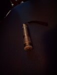
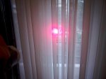
hi all,im new to the forum and also new to lasers.so i made my 1st cheap 650nm laser,i extracted the diode from a NEC 16x ND-3550A and used an adjustable 0-500ma driver,i used a very cheap lense from those 5mw flat diodes that selling on ebay(i know ill change this soon) and mount all of them on flashligh housing.i played with the potentiometer and set it around 200-250ma,the problem i got is when i try more current nothing happens the output power of the diode is not changing,i measured the driver with my multimeter and it does raises the current.i expected the diode to get brigher or die after that.the diode is always cool and i also do quick cycles on and off but when i set the current at 350ma it felt worm-hot.at current state the beam is visible at night on the sky and it can burn black things and light matches.so the question is why it doesnt accept more power?thanks for the help and sorry for my english :)


Joined
May 14, 2013
Messages
3,438
Points
0
Don't try more current, it will kill the diode. Every diode has a maximum current, if you go a little beyond that you may get a little more power but it will kill the diode or it will degrade over time, you also reach the fold back point where more current provides no increase in power, and beyond that there is usually a drop in power, this is about the time you will kill the diode.

Alan
 
Joined
Feb 21, 2016
Messages
475
Points
0
thanks for the reply now i understund the reason so i set it to around 200ma or allitle more,well thats a tought diode i even turned the potentiometer max and didnt broke:p so i also got 2 open diodes from burners that im gonna build them later,thanks for the great info
 

Pman

0
Joined
Nov 28, 2012
Messages
4,447
Points
113
Yeah, what PI said. You got lucky but congrats on a successful build. +REP for doing it yourself and being smart enough to ask some important questions.
 
Joined
Feb 21, 2016
Messages
475
Points
0
thanks,i did it focusable also and all i need right now is a better lens(waiting to arrive) that will also help on cooling cause its generates some heat right now and im very carefull on my of-off cycles
 
Joined
Sep 20, 2013
Messages
17,408
Points
113
I think it is great you tried to do this yourself and were successful. Especially if the diode is not pressed into a module, but stands alone to carry all the heat. Did you interrupt the circuit to the diode to measure your current? Pman's suggestion is very good if you are looking to build more in this wavelength.
 
Joined
Feb 21, 2016
Messages
475
Points
0
A metal lens holder will help just a little. For some really cheap good output diodes to have fun with take a look at these LPC-826. Cheapest I've ever seen them:
5pcs Mitsubishi 660nm Red Laser TO18 5 6mm LD Diode 200mW 300mW CW LPC826 | eBay
Just keep in mind that they are case negative.
i found a good source with alot of dead cds dvds roms and rw so i keep working on extractions,so far i already have 2 open diodes same as the listed on the link you posted,im have already ordered 3 housings to try them out and 3 drivers im also planning to build an ir laser only for burning purposes from cdrw

I think it is great you tried to do this yourself and were successful. Especially if the diode is not pressed into a module, but stands alone to carry all the heat. Did you interrupt the circuit to the diode to measure your current? Pman's suggestion is very good if you are looking to build more in this wavelength.
i mount the diode on those small 1-5mw 650nm laser diodes that selling on ebay dirty cheap(i had one dead)so i used some thermal adhesive to fit the diode there.no i used my multimeter paraller with diode so all the current is passing through the multimeter without
resistors,i just sorted the output current and messured it(i dont know if this can destroy the driver but i was trying it for around a sec each time)

im attaching photos from the laser(the photo is taken on daylight i tried on dark room also but my phone cant catch the beam that is visible on the human eye)the front part can be screwed or unscrewed to focus the beam.
 

Attachments

  • IMG_20160224_161815.jpg
    IMG_20160224_161815.jpg
    200.9 KB · Views: 56
  • IMG_20160224_161704.jpg
    IMG_20160224_161704.jpg
    197.7 KB · Views: 47
  • IMG_20160224_161924.jpg
    IMG_20160224_161924.jpg
    209.9 KB · Views: 43
Last edited:
Joined
Sep 20, 2013
Messages
17,408
Points
113
i

i mount the diode on those small 1-5mw 650nm laser diodes that selling on ebay dirty cheap(i had one dead)so i used some thermal adhesive to fit the diode there.no i used my multimeter paraller with diode so all the current is passing through the multimeter without
resistors,i just sorted the output current and messured it(i dont know if this can destroy the driver but i was trying it for around a sec each time)

Deadshadow, you cannot measure current in the way you described. To do it you must interrupt the circuit to the diode and put the ammeter in series with the diode and driver. Measuring current by paralleling the meter across the laser diode will do one of two things, depending on the setting of your meter. If it is set to volts DC, you will get the forward voltage that the diode is using to conduct. If you set the meter to the DC current, it will bypass the entire current around the diode and probably damage your driver. That is why the current is always set using a dummy load, or test load to adjust before connecting the laser diode to the driver. This dummy load can be easily built from a thread you can find on this forum. If you plan on doing this again. I would suggest you try to do it this way as I am unaware of any other method that can work. :)
 
Joined
Feb 21, 2016
Messages
475
Points
0
Deadshadow, you cannot measure current in the way you described. To do it you must interrupt the circuit to the diode and put the ammeter in series with the diode and driver. Measuring current by paralleling the meter across the laser diode will do one of two things, depending on the setting of your meter. If it is set to volts DC, you will get the forward voltage that the diode is using to conduct. If you set the meter to the DC current, it will bypass the entire current around the diode and probably damage your driver. That is why the current is always set using a dummy load, or test load to adjust before connecting the laser diode to the driver. This dummy load can be easily built from a thread you can find on this forum. If you plan on doing this again. I would suggest you try to do it this way as I am unaware of any other method that can work. :)
i set the multimeter on the A meter,it shorts a circuit and mesuring the the A passing through.thanks for the help next time ill conect one pin of the diode to the driver and my multimeter in series with driver and diode :)
:thanks:
 
Joined
Feb 21, 2016
Messages
475
Points
0
i recieved 2 housings and 1 driver and im currently working on the 2nd project with an open can diode but i have a problem on the current of the driver,the driver is this one 635nm 680nm Red Laser Diode Driver 3V 5 5V 1 Pcs | eBay

the problem is that the driver is going from 0 to 170ma normally but is it stays there no matter how much i turn it.if i mesure the current with the multimeter without a diode it has 450ma output but if i connect the diode it only outputs 170ma.i mesured the current in series with multimeter and diode
 
Joined
Sep 20, 2013
Messages
17,408
Points
113
The only way to set a driver current is to connect it to a test load in place of the laser diode. This test load can be easily built from six silicon rectifiers and a 1 ohm resistor. The rectifiers are connected in series, cathodes toward with the resistor and the free end of the resistor is the ground connection for the driver and a volt meter. For red select the anode of the third rectifier from the resistor as the positive connection for the driver. You can then measure the voltage drop across the resistor and millivolts will equal milliamps.
 
Joined
Feb 21, 2016
Messages
475
Points
0
thanks i found out that this driver needs over 7volts to work(it is false advertist).i mesured the current corectly but i overcurrent 2 diodes and went leded.i used 400ma on open can diode and 350ma on long closed diode,i thought those 2 can handle such current with a good and quick cycles.now i got a normal closed can diode that set the current on 220ma and so far is working good,any suggestions on the recomented currents for dvdrw diodes?thanks for all the help i apreciated :yh:


Top