Welcome to Laser Pointer Forums - discuss green laser pointers, blue laser pointers, and all types of lasers

LPF Donation via Stripe | LPF Donation - Other Methods

Links below open in new window

ArcticMyst Security by Avery

A little help with this

Joined
Dec 11, 2012
Messages
38
Points
0
So i wanted to build a laser driver for my LPC-826 laser driver and i asked on this forum to give me some advice and someone said i needed to ditch everything except the LM317 the capacitor and get a new resistor
This is what i had in mind to build
LM317%20components01.jpg


But he said to make this cause it was better but i dontknow how to calculate what resistors and capacitors and stuff i need so can you guys help me
I would ask him but i feel like im bothering
This.
driverddl.jpg

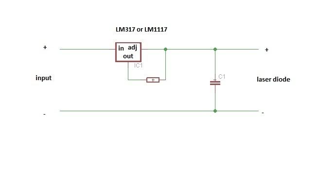
So yeah the point of the question is what kind of capacitor and resistor do i need


Joined
Sep 12, 2007
Messages
9,399
Points
113
The capacitor value doesn't matter. You can pick pretty much anything 0.1µF or more and it will be fine.

The lm317 keeps about 1.25V across out and adj pins so you use ohm's law:

1.25 / (Desired current in amps) = resistance

Of course, the value you get will not likely match standard values available, so you can round up or use series/parallel combinations of other resistors.
 
Joined
Sep 12, 2007
Messages
9,399
Points
113
Yes. Most people like to run those diodes harder, but 250mA is also acceptable.
 
Joined
Dec 11, 2012
Messages
38
Points
0
If i want it more mA i just put more resistors?
Sorry for bothering im just a noob that has laser fever
 
Joined
Feb 5, 2008
Messages
6,252
Points
83
You should've asked all this stuff in PM rather than opening a new thread ;)

In short,

No, if you want more mA, you need less resistance. Try putting some numbers in the formula and see what comes up.

For example see what current you get if you have 10 ohm resistor.

1.25 / 10 = *** mA
 
Joined
Feb 5, 2008
Messages
6,252
Points
83
Nah man, you can ask me anything anytime :)

Yep, that's correct.

Formula also works other way around. For example if you want a current of 350mA, or 0.35 A,

1.25/0.35 = your resistor.
 
Joined
Sep 12, 2007
Messages
9,399
Points
113
More resistors in parallel means less resistance, and therefore more current. The original design used two 10Ω in parallel for 5Ω (presumably because 10Ω resistors are common). You can add a third 10Ω for 3.3Ω (375mA) and a fourth for 2.5Ω (500mA)
 
Joined
Oct 26, 2007
Messages
5,438
Points
83
Before you start wiring stuff up, please understand Ohm's Law, or otherwise you won't understand how to adapt that driver for your needs. In particular, the LM317 provides 1.25V from the Output to ADJ pin. So using that, use Ohm's law to figure out the current you need or want.
 
Joined
Dec 11, 2012
Messages
38
Points
0
Parallel is side by side no?

And i would like to get around 250mA for 150mW so V=I/R
R=5 (i saw somewhere else that if you put two resistors in parallel it wont give you the adds of those 2 but the half so if two 10 ohm resistors in parallel is 5 ohms right???.)
V=1.25

1.25/5= 0.25Ax1000 =250mA
This is all i understand up to now
 
Last edited:
Joined
Feb 5, 2008
Messages
6,252
Points
83
Correct.

250mA is a nice conservative current for your diode, it shouldn't heat up as much as it would if hard driven, and it's surely lasting a long time.

Not to mention the battery life is going to be much higher too.

Speaking of which, 9V battery is a bad choice for a battery.


Top