Welcome to Laser Pointer Forums - discuss green laser pointers, blue laser pointers, and all types of lasers

LPF Donation via Stripe | LPF Donation - Other Methods

Links below open in new window

ArcticMyst Security by Avery

How to power a red diode

Joined
Mar 5, 2012
Messages
161
Points
18
Ive got a red diode im trying to power but not getting it to work.

From my understanding is that a red diode must be continuously grounded.
So does that mean that the 3rd pin must be grounded?

The diode is not in a host or a machine. So its not grounded.

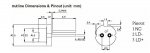
I have LD+ connected to the positive
Assuming that LD- must be the negative
What do I do with the NC pin?


Joined
Mar 5, 2012
Messages
161
Points
18
what diode and driver are you using? and what are you going to use to power it?

ML101U29 diode
adjustable x-driver at 200ma

and 12v power supply.


I just need to know if the red diodes have to use the 3rd pin or not.
 
Last edited:

oahu99

0
Joined
Feb 23, 2014
Messages
140
Points
18
You don't have to use the third pin. It is the pin for a photo diode in the diode itself.
By the way continous ground means the diode negative goes directly to the battery negative.
 
Last edited:
Joined
Mar 5, 2012
Messages
161
Points
18
You don't have to use the third pin. It is the pin for a photo diode in the diode itself.
By the way continous ground means the diode negative goes directly to the battery negative.

well in a handheld laser, ive connected the negative directly to the driver. So whats so different about this setup im using?

I have a 12v wall power supply that is connected to the driver which is connected to the diode. The diode is not installed in a host or anything.

So what is it that Im doing wrong that isnt letting the diode work.

Here are the actual diode specs

size : 5.6 mm ( TO18 package)
service life : > 10000 hours
output wavelength : 660nm
output power CW : 130mW
output pulse: 350mw
working voltage : DC= 2.2-3V
working current : I < 340mA
 
Last edited:

oahu99

0
Joined
Feb 23, 2014
Messages
140
Points
18
What exactly is the diode doing?
Is it creating any light at all?
Is the diode still getting hot?
The diode could be dead, or something like that. I need a bit more detail to troubleshoot.
 
Last edited:
Joined
Mar 5, 2012
Messages
161
Points
18
What exactly is the diode doing?
Is it creating any light at all?
Is the diode still getting hot?
The diode could be dead, or something like that. I need a bit more detail to troubleshoot.

Its doing nothing. No light, no heat. Ive tried 4 different diodes of the same one and nothing.
 

Teej

0
Joined
Apr 16, 2014
Messages
520
Points
48
Its doing nothing. No light, no heat. Ive tried 4 different diodes of the same one and nothing.

Did you test to be sure the leads from the power supply were supplying what each lead was supposed to?

If your LED are not polarity protected by the set up, reversed leads can kill them instantly.
 
Last edited:
Joined
Mar 5, 2012
Messages
161
Points
18
Did you test to be sure the leads from the power supply were supplying what each lead was supposed to?

If your LED are not polarity protected by the set up, reversed leads can kill them instantly.

Well if you mean did I test that the diode is getting 12v? Yes
Did I test the driver to make sure the settings were correct? yes at 200ma.
are the positive and negative leads soldered right? yes
Did I check which was positive and which lead was negative from the power supply? yes.

so not sure why its not working properly
 
Last edited:

Teej

0
Joined
Apr 16, 2014
Messages
520
Points
48
I meant did you check that the leads were not reversed for that diode...IE: Everything looks fine but the outputs are not correct.

I was looking for a way to explain why you got NOTHING from any of them. One bad diode, etc, sure....but I think you tested a few.

So, the two basic ways for nothing to work are:

either your equipment is at fault

or

ALL of your diodes are bad.


If you find your equipment is fine, then, return the diodes as they sent you a bad batch.


I assume you can use your equipment to test a diode that you know works from something..., and, make sure the polarity of the red diode is the same as the polarity of the known working diode.

From here...I can't be as helpful as I'd like, but, to me, the above would be my starting point.

:D

As for the 12 v.....are you throttling that down to the working voltage of the diode?
 
Last edited:
Joined
Jan 14, 2011
Messages
424
Points
0
Continuous ground means that power - (batt -) on the driver and output - (LD-) are common (connectec together with nocircuitry in between, all the electronics of the driver are on the positive side)....
 
Joined
Mar 5, 2012
Messages
161
Points
18
I meant did you check that the leads were not reversed for that diode...IE: Everything looks fine but the outputs are not correct.

I was looking for a way to explain why you got NOTHING from any of them. One bad diode, etc, sure....but I think you tested a few.

So, the two basic ways for nothing to work are:

either your equipment is at fault

or

ALL of your diodes are bad.


If you find your equipment is fine, then, return the diodes as they sent you a bad batch.


I assume you can use your equipment to test a diode that you know works from something..., and, make sure the polarity of the red diode is the same as the polarity of the known working diode.

From here...I can't be as helpful as I'd like, but, to me, the above would be my starting point.

:D

As for the 12 v.....are you throttling that down to the working voltage of the diode?

As far as I know its throttled down. I think the driver does that.
12v going into the driver and 7.35 coming out which is set at 200ma. and i did test the driver.
Its got power everywhere, even at the diode leads. Just the diode isnt turning on

Heres a layout of the laser diode
Ive got positive to pin 3 and negative to pin 1

EDIT: Are you guying saying that since this has a continuous ground that the ground from the diode itsself has to be directly connected to the 12v power supply?
 

Attachments

  • 2010321105235267.jpg
    2010321105235267.jpg
    35.2 KB · Views: 153
Last edited:

Teej

0
Joined
Apr 16, 2014
Messages
520
Points
48
What's the voltage at the connections to the diode?

IIRC, its designed to so that the case is part of the connection, so a jumper might be needed across pins, etc.

Do you know which pins do what?
 
Last edited:
Joined
Apr 1, 2013
Messages
32
Points
0
pin 3 is pos. and 2 is neg.I believe pin 1 is the photo diode
 
Last edited:
Joined
Mar 5, 2012
Messages
161
Points
18
What do you mean a photo diode? What is that? Is thst like used for scanners or something?
 
Joined
Apr 1, 2013
Messages
32
Points
0
You might want to ask someone more knowledgable but what I understand is you only need 2 of the three pins..one's positive one's negative and the other is a photodiode that limits the current output..but I'm still new to this so someone else chime in please


Top