Welcome to Laser Pointer Forums - discuss green laser pointers, blue laser pointers, and all types of lasers

LPF Donation via Stripe | LPF Donation - Other Methods

Links below open in new window

ArcticMyst Security by Avery

Flexdrive killing LPC-826

Joined
Nov 26, 2011
Messages
86
Points
8
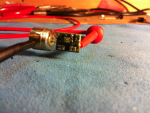
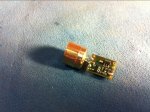
So I have no killed two diodes the exact same way, and I can't figure out what is going wrong. I have a micro flexdrive from cajunlasers, an LPC-826 from cajunlasers, a Mastech power supply, and a home-built test load. Here is my procedure:

1. Hook diode in aixiz module up to power supply, feed it 400mA with. All good.

2. Connect four diodes (1N4004s from radioshack) up on my test load, connect my + and ground up to the flexdrive, put multimeter test leads up to resistor (1-ohm 10-watt from radioshack), run 4.0V through flexdrive. Reads 395mA, power supply is saying it's putting out 0.38A, so just about the same. All good.

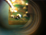
3. Short + and - to diode out on flexdrive, solder laser diode pins to proper places on flexdrive, hook flexdrive up to power supply (which I have not touched since testing with the test load, and turn on. Laser flashes bright for a fraction of a second them dims down to almost nothing, I can see a point with a line through it, so I assume it is LED'd. Power supply says it's putting out 0.49A. :wtf:

4. Hook diode directly back up to power supply, feed it 400mA, and I get the same dim dot with a line through it.

I do all of this with a grounding wrist strap on. I've gone through this exact procedure twice now with the exact same result. I have one more diode to test this on before I give up altogether. Can anyone help me figure out what's going on?

Here's a diagram of my test load circuit:

+ in----1N4004----1N4004----1N4004----1N4004----1ohm, 10watt resistor---- gnd out

The positive current is fed through the side of the 1N4004's with no band and out through the side with the silver band.

It's based off the diagram in this thread: http://laserpointerforums.com/f51/how-make-selectable-dummy-load-very-depth-64585.html

Thanks,
Shep
 
Last edited:


Joined
Dec 11, 2011
Messages
4,364
Points
83
What's the tolerance on that 1ohm 10watt resistor? The only thing I can think of is that it is not really 1-Ohm and thus your Flexdrive is actually set to be putting out more current.
 
Joined
Oct 24, 2009
Messages
2,555
Points
48
did you try and measure the current with your multi meter set to 10a?
 
Joined
Nov 26, 2011
Messages
86
Points
8
Merged consecutive posts

The tolerance is 10%; however, when I measure it with my multimeter, it comes out to be 1.5ohm... I guess that is the problem. Any way to correct this without getting a new resistor? It's the only kind of 1-ohm resistor I could find anywhere around me.

did you try and measure the current with your multi meter set to 10a?

I didn't try to do this, I was under the impression that it was bad to directly measure the current from a flexdrive without a test load?

EDIT: I measure my resistor to be about 1.3-1.4ohms, so I'm going to assume 1.35. Therefore, if I want 350mA (to be more conservative in case of error until I can get a better resistor), because I=V/R:

350mA = V/1.35ohm, V=350/1.35ohm ~=250mV

So, I should measure 250mV across the resistor when setting the current for it to be ~350mA. Does my logic make sense?

I also have some 10ohm resistors which I am sure are almost exactly 10ohm. Would it be more accurate to use these then measure 35mV across the resistor?
 
Last edited by a moderator:

Blord

0
Joined
Dec 24, 2007
Messages
5,356
Points
0
You can measure the current with your multi meter. Just put the diode back to the flexdrive and set the DMM in series with the circuit. You read directly the current thru the diode.
 
Joined
Nov 26, 2011
Messages
86
Points
8
SKIP the voltage reading on the resistor. This is a cheesy way to do this. I know its easy and popular, BUT you really need to put the meter "In series" with the load. Take the Neg output to the diode / test load put it to the NEG lead on the multimeter. Take the POS lead of the muiltimeter and connect it to the NEG lead on the diode. Connect the POS out from the P/S and hook it to the POS lead on the diode / test load. Make sure the mulitmeter is on 10A DC current and the POS lead of the multimeter is hooked to the "I=10A" hole.
And who gives a rats ass what the resistor reads. It doesnt matter anymore...

I don't quite get what you're saying. It sounds like the negative and positive leads of the multimeter are both connected to the wire that goes from the flexdrive to diode+, and the positive power supply goes directly into the diode, thus avoiding the flexdrive altogether. This doesn't seem to make sense...

Did you use your current limited power supply we talked about yet? Skip the flexdrive set the correct voltage, limit the current to 350mA on you power supply output with the dummy load. Then use JUST the power supply making sure the polarity (double check datasheet) is correct on the diode. This should work. If it does flexdrive is bad.

Yes, I used my power supply to test out the diode (current knob set to 350mA, voltage knob all the way up so that it just uses whatever voltage the diode takes), and it worked fine.


You can measure the current with your multi meter. Just put the diode back to the flexdrive and set the DMM in series with the circuit. You read directly the current thru the diode.

I tried doing this, but I just got a reading of 1.4A which I highly doubt is correct.
 
Last edited:
Joined
Jan 14, 2011
Messages
3,816
Points
63
Note that, when you turn off your power supply, you may not be discharging the capacitors in it... (it may not have built in bleeder caps). I have had the problem before where it gives a current spike if you don't turn the current down all the way and then slowly ramp it up again.
 

Blord

0
Joined
Dec 24, 2007
Messages
5,356
Points
0
I tried doing this, but I just got a reading of 1.4A which I highly doubt is correct.

You have been blowing up two LPC-826 diodes. The diodes can handle current of 600mA. At 1.4A they flash and turns into leds.
Looks like the reading is correct. The question is why the driver is outputting 1.4A ? Did you turn the pot on the flexdrive all the way to the minimum ?
A slight touch and the pot may turn to the other side and deliver max current.
 
Joined
Nov 26, 2011
Messages
86
Points
8
So I ended up setting my flexdrive to the ~100-412mA range thinking I couldn't go wrong with it, there was no way the diode would blow and I could just set the potentiometer by looking at the light. Nope, same thing, last diode blown. I give up.
 
Joined
May 25, 2010
Messages
3,655
Points
0
So I ended up setting my flexdrive to the ~100-412mA range thinking I couldn't go wrong with it, there was no way the diode would blow and I could just set the potentiometer by looking at the light. Nope, same thing, last diode blown. I give up.

Can you show a picture of how you are connecting it to your diode.?

In other words take a picture of the diode in the module how its connected to the driver and then how the driver is connected to your supply.
 
Joined
Nov 26, 2011
Messages
86
Points
8
Can you show a picture of how you are connecting it to your diode.?

In other words take a picture of the diode in the module how its connected to the driver and then how the driver is connected to your supply.

Here are some pictures of the setup... I connected it to the power supply by connecting the negative lead to the case and positive to a solder blob on the end.

I also noticed that there seems to be a component missing next to the positive diode pin. I included a super-close-up of the missing area (taken through an aixiz lens with my iPhone camera :D)

-Shep
 

Attachments

  • Screen Shot 2012-01-12 at 8.34.13 PM.png
    Screen Shot 2012-01-12 at 8.34.13 PM.png
    748.1 KB · Views: 455
  • Screen Shot 2012-01-12 at 8.34.19 PM.png
    Screen Shot 2012-01-12 at 8.34.19 PM.png
    692.4 KB · Views: 449
  • Screen Shot 2012-01-12 at 8.38.30 PM.png
    Screen Shot 2012-01-12 at 8.38.30 PM.png
    614.1 KB · Views: 726
Joined
Nov 26, 2011
Messages
86
Points
8
The LPC-826 is case-negative so connecting the negative lead to the case is OK in this case (no pun intended). See the micro flexdrive v5 manual: http://hacylon.case.edu/ebay/laser_diode/MicroFlexDrive_V5_manual.pdf
The first wiring diagram is the setup I have.

I know that there is no way to measure current in this case; I was just setting it up in the way that was simplest, easiest, and how I was going to put it into my host. I don't intend to be measuring current once it's placed in my host.

I just noticed your diagram. Thank you for making that; I'll try it tomorrow. I'll run it through my test load and make sure that the flexdrive is erratic/dead. However, I'm not exactly sure what the function of the missing capacitor was. I think it's just for smoothing out the current, so it should run fine without the piece, correct? I do know that current still flows without the capacitor, as it ran through to kill my diode. I just can't seem to pin down how much current is flowing through.

I know that it is an issue with the flexdrive, as I tested the diodes on my CC/CV variable power supply beforehand. However, I don't know if it's that the flexdrive is actually broken or that I am setting it to the wrong current, which is what I am trying to figure out.

Before plugging this diode into the flexdrive, I made sure that one of the older ones ran off it first. It didn't get warm, so I assumed it was at a relatively safe current. Perhaps the missing capacitor has to do with the sudden jolt of current right when the diode is plugged in?

Shep


Top