Welcome to Laser Pointer Forums - discuss green laser pointers, blue laser pointers, and all types of lasers

LPF Donation via Stripe | LPF Donation - Other Methods

Links below open in new window

ArcticMyst Security by Avery

First 660nm in progress

Joined
Apr 23, 2011
Messages
212
Points
0
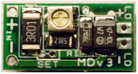
During testing and operation I learned that the rkcstr driver produced a lot more heat operating near 8.0 VDC than it does at 7.5.

hence linear driver ;)

awww no 445? ahh well.. Lookforward to seeing your next build.


yzer

0
Joined
May 10, 2011
Messages
85
Points
0
Well, there is a 445 in my future but the green will come first.
 
Joined
Mar 26, 2010
Messages
3,220
Points
0
You have to remember that just because the 445's will run at 2A and put out almost 2W... There's nothing forcing you to ram that much current through it. One of my favorite lasers is a 445 in a trustfire ef23 1xAAA host.. It does arond 50mW when running off a decent quality AAA. Though it'll do about 400mW using a 10440 Li-ion heh. But the stock drivers have high and low modes, so in low, it's still around 50mW.

100_0728.JPG


Here is a beamshot with fog of it running at around 50mW (the one in the middle).. The other two are 473nm and 405nm.

IMG_0265.JPG


Also did a cute little 45mW 532nm in a MXDL host.. Runs off a 10280. :D I did one in a EF23 too but that green module sucked.

100_0746.JPG
 
Last edited:
Joined
Apr 23, 2011
Messages
212
Points
0
Know of any local place to get Arctic Alumina? Couldn't find any thermal adhesive around here. Another pain is thermal adhesive generally comes in such small quantities. Doesn't last too long.
 
Joined
Mar 26, 2010
Messages
3,220
Points
0
I've actually never used arctic alumina before. I have a big tube of thermal silicon adhesive that I got from DX that i've been working through for a while.
 
Last edited:

LaZeRz

0
Joined
Feb 19, 2011
Messages
2,549
Points
63
What green module is that Qumefox?

It has razer sharp divergence...
 
Joined
Mar 26, 2010
Messages
3,220
Points
0
Most cheap greens do have a thin beam like that within a foot of the laser. heh. The module was originally out of a cheap DX '50mW' laser. I machined off the whole front of the housing just past the crystal set and I'm using a normal aixiz acrylic for collimation since with it's short focal length I can get it much closer to the crystal set.. which reduces module length. All in all I got the total module length including driver down to just over 30mm.. Short enough I could cram in a 1x AAA MXDL host heh. Who else has a sub 4" long 532? :D I haven't measured it yet, but the divergence after doing this is only 'average'. Looks to be somewhere between 1 and 1.2 mRad.
 

yzer

0
Joined
May 10, 2011
Messages
85
Points
0
Know of any local place to get Arctic Alumina? Couldn't find any thermal adhesive around here. Another pain is thermal adhesive generally comes in such small quantities. Doesn't last too long.
I found it at a Fry's store. They also sell it online.
 

yzer

0
Joined
May 10, 2011
Messages
85
Points
0
I am updating this thread with some more detailed information. Another LPF member is building a 660nm red with the same LOC LPC-815 laser diode and the rkcstr Micro-Drive. He wants specifics regarding the test load and driver adjustment. I'll add some other information useful for anyone else trying to build a red with the same laser diode and driver.

Power chart for the LPC 815 laser diode. Save this chart, print it use it at the workbench. http://laserpointerforums.com/f50/red-laser-diode-roundup-36202.html

This is the rkcstr Micro-Drive. Power connects to the + & - solder pads marked IN. The test load connects to the pads marked LD + & -. After driver current is adjusted with the pot in the middle of the driver the laser diode is soldered to LD + & -. The solder pads are on both sides of the circuit board so that you can make temporary connections to the Micro-drive during adjustment by using simple test leads. Using test leads saves you from soldering the test load to the driver and desoldering it after the adjustment is done.
rkcstrcrp.jpg


This is the test load for the LOC LPC-815 laser diode. It is four 1N4001 rectifier diodes connected in series with a 1 ohm resistor. The diodes and the resistor are soldered together. There is a band printed next to one end of the diode body. Make sure that the diodes are connected so that the banded ends are closest to the resistor. The banded ends are the - (negative) end of the diodes.

Usually a 1/4-watt carbon film resistor is specified for this test load. I bought these parts at Radio Shack where they didn't have any carbon film 1 ohm resistors. I bought a 10-watt wire-wound resistor instead and it works just fine.

The diode side of the test load connects to the driver at LD+ and the resistor side connects at LD-.
009a.jpg


Here is the test load and DMM set up with test leads. Moving from left to right in the picture below: test leads ready to connect to the Micro-Drive. Red goes to LD+, Black to LD-. Test leads are properly connected across the resistor. The DMM is an entry level Radio Shack DMM.

I like to have all connections made and the DMM turned on before firing up the driver for adjustment. That way I can see the peak value at startup and watch it settle down a couple of seconds later.

The DMM is set for mV for tests with this test load. The value on the meter in volts will be equal to driver output in amps with this test load. Example: 350mV on the meter = 350mA output from the driver.
002.jpg


After you have completed driver adjustment and are happy with the output, turn off power, disconnect the test leads and solder the laser diode to the driver. A word of WARNING here: A current charge will remain in the driver capacitor after the driver is turned off. If you touch the laser diode to the LD + & - pads before discharging this current you will probably destroy the laser diode. To discharge the driver: short circuit the driver by touching the ends of a single wire or test lead to the LD + & - pads.

Here is another way to run adjustment tests if you have a better quality DMM that can handle the current (the Radio Shack DMM shown above can't). This slightly better old Equus DMM can handle up to 10 amps, more than enough for the current required by the LPC-815 diode. Typically, these better quality DMMs have multiple jacks for the test probes. Simply set up the DMM to an upper mA range and connect the meter directly to the LD + & -. No test load is needed.
014a.jpg


Finally, some of the tools that came in handy for me during this DIY laser project. I don't show the test leads here or tools that I needed for working on the host and heat sink like a file, hacksaw, belt sander and drill.
016a.jpg


The LOC LPC-815 laser diodes are not expensive and can be used by most anyone with basic tools and skills to a make a high quality DIY laser. For not much more money than you need to purchase a 200mW Chinese laser that is probably underspec you can build a better laser yourself. DIY gives you the opportunity to be creative with design and come up with a custom laser.
 
Last edited:

yzer

0
Joined
May 10, 2011
Messages
85
Points
0
Oh, yeah. I've had some of those tools for many years having worked on old tube-type military radios, boats, cars and the house. The handy hands are at least 15 years old: they didn't come with the magnifying glass back then. That old tin of Burnley soldering flux is ancient: you don't need to use much of it.
 

yzer

0
Joined
May 10, 2011
Messages
85
Points
0
The host is a 2xAA Mini Maglite flashlight (krypton light bulb: not LED). This host is not that easy to work with but it made for a very nice laser. A red LPC-815 laser can be made from a much smaller host using smaller batteries or a boost-type driver with a single battery but I wanted the Minimag host. The 2x14500s give it a nice heft and battery capacity. The finished host is still fairly front-heavy even with the two 14500s.
 
Last edited:
Joined
Aug 15, 2011
Messages
311
Points
0
OK, So you put in 3V and put the current to...?
do you happen to have a laser power meter to test it's mW output?


Top