qumefox
0
- Joined
- Mar 26, 2010
- Messages
- 3,220
- Points
- 0
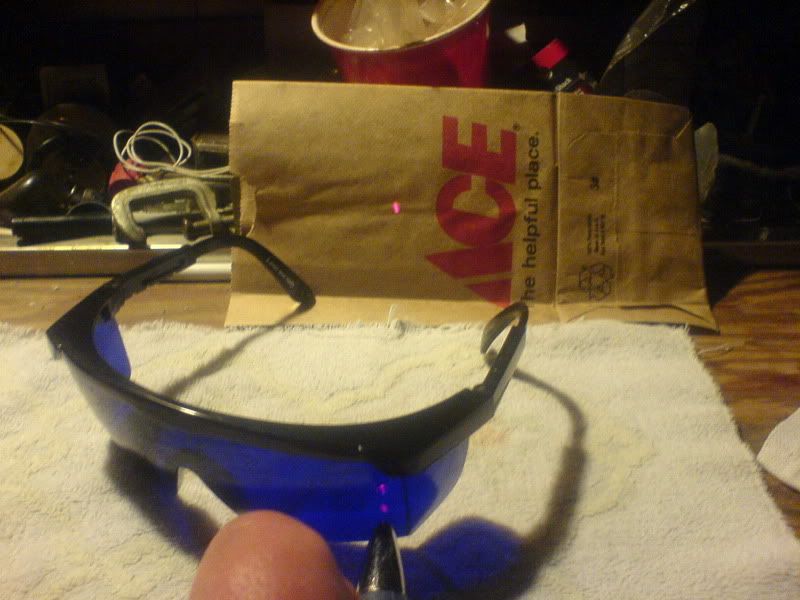
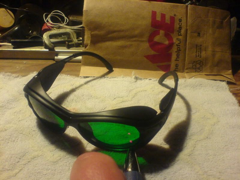
All the chinese goggles I have that look like that, regardless of color, have been crap. I think the *best* of those style i've tested have had an OD of 0.7.


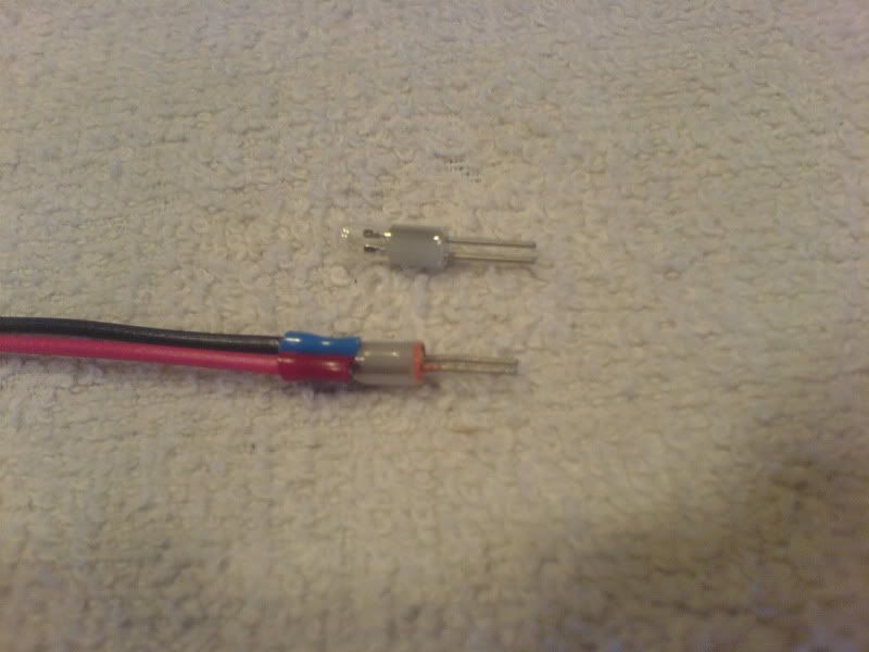
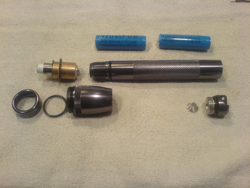
In this build the socket connection is between the batteries and driver input. The laser diode is soldered directly to the rkcstr driver output.Another thing I just spotted that I missed the first time. Socketed diode connections equal dead diodes in the long run.. just FYI heh. You mentioned already killing one diode and driver due to bad connections, and a socket is a bad connection waiting to happen. Sockets are fine before the driver.. just not after them.
 The socket connection in the MiniMag isn't ideal but it seems to work fine. In the MiniMag the socket and switch assembly rotates along with the head. It's the contact on that rotating socket I would be most concerned about but it works OK, too. No sign yet of bad contacts anywhere.
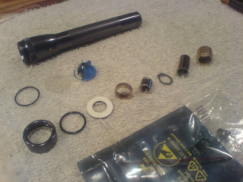
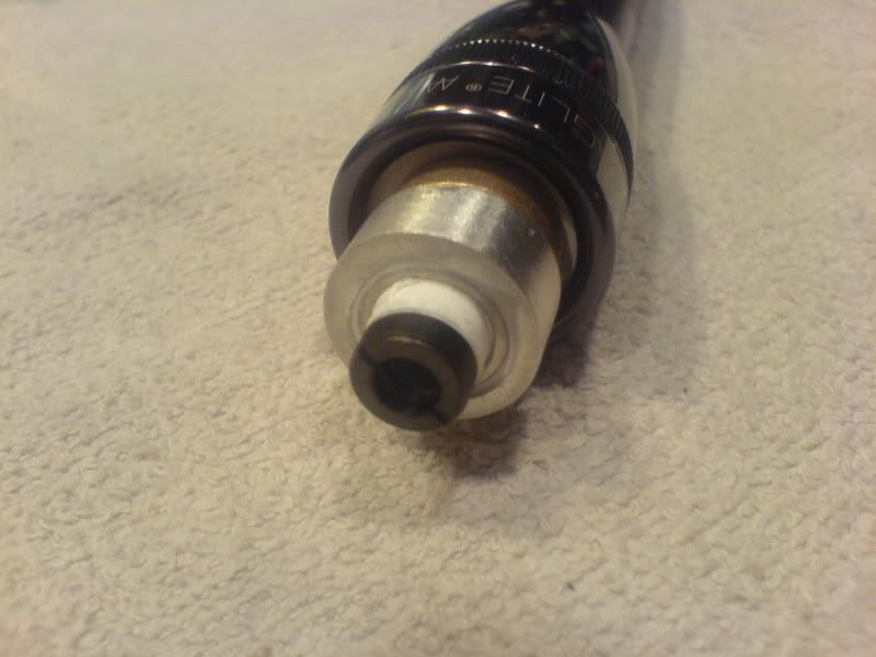
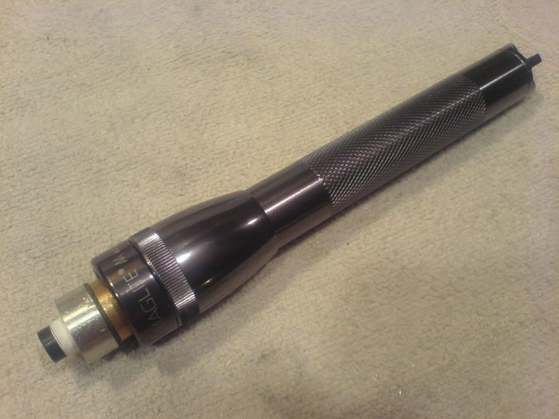
Thanks, rd. The diode heat sink is another Ace Hardware item from the fastener department. It's an aluminum cable stop 1/4" that cost $2.19. I cut it down to size and drilled out the 1/4" hole to fit the Aixis module.Great documentation yzer! Looking forward to see what you do in the future! Congrats on the successful build. You should try a 2W blue next =D . Also, nice idea with the heat sink. I'll have to consider that. Aloot cheaper then many of the other options out there.
In this build the socket connection is between the batteries and driver input. The laser diode is soldered directly to the rkcstr driver output.
Qumefox, mind explaining what you mean by socketed diode connections? I'm rather curious as to what that is... hopefully i'm not doing it.
