Welcome to Laser Pointer Forums - discuss green laser pointers, blue laser pointers, and all types of lasers

LPF Donation via Stripe | LPF Donation - Other Methods

Links below open in new window

ArcticMyst Security by Avery

driver help

Joined
Feb 2, 2009
Messages
33
Points
0
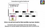
hi i need help i dont know how to check the ma of the test load while connecting it to a rkcstar driver!!!!!!

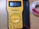
i have a multimeter but dont know where to conncet it and what setting to put the dmm at

please help asap


Joined
Jul 24, 2007
Messages
2,749
Points
0
Which test load? If the one below instructions are on the drawing..

Regards rog8811
 

Attachments

  • test_load01_008.jpg
    test_load01_008.jpg
    41.2 KB · Views: 90
Joined
Aug 30, 2008
Messages
6,891
Points
83
if your using rkcstr's test load, put the dmm on each side of the 1ohm resistor, then take the reading where 1mW = 1mA
 
Joined
Dec 23, 2008
Messages
3,948
Points
63
i just made my first test load yesterday, like the picture that rog posted. I hooked it up for the phr configuration to a rkcstr driver (adjust blu ray one). for the power source i have a 120vac box with a rectifier and a variac. I put the output voltage to less than 9vdc. I hooked up the driver and test load, then set my mm to mv but i didnt get a reading. :-[ and when i put the voltage meter back on dc test i checked the out put volts at 8.5. any help would be greatly appreciated.


michael
 
Joined
Nov 7, 2008
Messages
5,725
Points
0
^Check your diodes to make sure their polarity is correct. Also there could be a problem with your driver..
 
Joined
Dec 23, 2008
Messages
3,948
Points
63
thanks elektro. i'll do that now. this electronics stuff is so new to me. :-/


michael.
 
Joined
Sep 20, 2008
Messages
17,622
Points
113
chipdouglas said:
i just made my first test load yesterday, like the picture that rog posted. I hooked it up for the phr configuration to a rkcstr driver (adjust blu ray one). for the power source i have a 120vac box with a rectifier and a variac. I put the output voltage to less than 9vdc. I hooked up the driver and test load, then set my mm to mv but i didnt get a reading.  :-[ and when i put the voltage meter back on dc test i checked the out put volts at 8.5.  any help would be greatly appreciated.


michael

What exactly are you using as power to the driver board...

Jerry
 
Joined
Dec 23, 2008
Messages
3,948
Points
63
hey jerry. i work with circuit breaker and transformers so i have lots of parts. i mad an ac/dc power supply with a toggle switches for straight ac power and to get the dc i put in a rectifier and a variable transformer from 0vdc to 125vdc. but i only used that to set the ma on my driver with the above mentioned test load.

michael.
 
Joined
Sep 20, 2008
Messages
17,622
Points
113
chipdouglas said:
hey jerry. i work with circuit breaker and transformers so i have lots of parts. i mad an ac/dc power supply with a toggle switches for straight ac power and to get the dc i put in a rectifier and a variable transformer from 0vdc to 125vdc. but i only used that to set the ma on my driver with the above mentioned test load.

michael.

If I understand correctly.... You have 120VAC going to a single rectifier Diode that is
fed into a Variac to reduce the Voltage to a level that is usable...(no other electronic parts
in the Power Supply setup)
Is that correct.... :-? :-?

Jerry
 
Joined
Dec 23, 2008
Messages
3,948
Points
63
yes. if this is bad for testing please let me know. because i made the box for a totally different purpose.
 
Joined
Sep 20, 2008
Messages
17,622
Points
113
Well.... there are 2 problems...
The first is about safety.... You are not isolated from the Main 120Volts
house current... you risk electrocuting yourself...
You should have at least a 120VAV to 120VAC isolation transformer...

The second problem is that you do not have 9Vdc... what you have is
Half Wave ripple DC...
The single diode is chopping every cycle of the 60 cycles in half...
You are only getting... +VDC then 0VDC then +VDC then
0VDC and so on.... 60 times a second... Your DC is pulsing...

What you need is a Bridge Rectifier (made up of 4 diodes) that will give
you Full Wave ripple DC....
Then you need to filter the DC with a capacitor of around 1000uF to 4000UF
at the proper Voltage of your maximum PS voltage (times 2 is a good safety
margin)...
I would suggest getting a 120Vac to 12Vac Transformer as the input power
source instead... it is much safer and the Capacitor will be much cheaper...
a good voltage rating for the Electrolytic Capacitor would be 25Vdc.

You would use your Variac before the 120Vac to 12Vac step-down transformer...

For an Electronic LD Driver to work properly... you need clean filtered
DC...  :cool:

Jerry
 
Joined
Dec 23, 2008
Messages
3,948
Points
63
geez. i will definately do that. i set my ma it took no more the 5 seconds. i still works when i hook up the ld. actually, never mind.i'll re-test with my batteries. im gonna use 3- 3volt batts.


thanks
michael
 
Joined
Nov 7, 2008
Messages
5,725
Points
0
chipdouglas said:
i feel like sticking my head in the sand!!!!!

EDIT: Sorry Jerry, posted this at the same time apparently..

Well don't stick your head in the sand..

The only problem I see with your setup is that IMHO the PS could use more rectification, like a half- or full-wave bridge.. A single diode will give you "pulsed DC" where part of the positive half (everything above .7V) of the incoming sine wave is passed by itself, leaving a gap where the negative half of the wave used to be. Ideally you'd want a smoother DC signal than this, which can be had using a full-wave bridge rectifier and a filter capacitor. Using your setup shouldn't harm your laser diode since the driver you are using will smooth out much of the ripple you're seeing as well as safeguard against overcurrent. The laser diode's ouput is most likely pulsating slightly with the incoming signal, since your driver's filtration circuitry most likely isn't perfect. Since this is occurring at a frequency of 50-60Hz, it is probably undetectable with the human eye.

While I am a huge fan of DIY, a quick easy solution to these problems is to use a 9VDC wall wart to power your driver..
 
Joined
Sep 20, 2008
Messages
17,622
Points
113
chipdouglas said:
geez. i will definately do that. i set my ma it took no more the 5 seconds. i still works when i hook up the ld. actually, never mind.i'll re-test with my batteries. im gonna use  3- 3volt batts.


thanks
michael

Here is a link to a Circuit that will get you started... you only need to build it
up to the LM350 Regulator... you don't need the rest of the parts for what
you want to do..

http://www.discovercircuits.com/DJ-Circuits/18VPS1.htm

[Edit] And like ElektroFreak posted... using a 9VDC wall wart would be even simpler..

Jerry
 
Joined
Feb 23, 2008
Messages
2,832
Points
48
chipdouglas said:
i just made my first test load yesterday, like the picture that rog posted. I hooked it up for the phr configuration to a rkcstr driver (adjust blu ray one). for the power source i have a 120vac box with a rectifier and a variac. I put the output voltage to less than 9vdc. I hooked up the driver and test load, then set my mm to mv but i didnt get a reading.  :-[ and when i put the voltage meter back on dc test i checked the out put volts at 8.5.  any help would be greatly appreciated.


michael
dont use the mv setting...on my dmm the setting to use is the 2v setting...
 

Attachments

  • 0212091404.jpg
    0212091404.jpg
    88.1 KB · Views: 85


Top