Welcome to Laser Pointer Forums - discuss green laser pointers, blue laser pointers, and all types of lasers

LPF Donation via Stripe | LPF Donation - Other Methods

Links below open in new window

ArcticMyst Security by Avery

Advice on wiring diode in flashlight host

Joined
Jun 12, 2009
Messages
35
Points
0
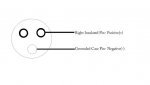
I am building myself my first red laser and I am using an lpc815 LOC diode into an Ultrafire c3 flashlight host, I have soldered the +ve and -ve connections onto the diode which is all ok, I have left the 3rd pin (case pin??) unconnected, when fitting the diode in its module into the flashlight does it need to be electrically insulated from the flashlight housing which I believe acts as the -ve connection from the battery to the driver, I am hoping that the diode is OK if not insulated from the flashlight case. Thanks for your help


Joined
Oct 11, 2008
Messages
150
Points
0
Well it depends on your host but most likely yes it is. But I don't think that you will need to insulate it. But dont take my word for it. Wait for a smarter member to reply.
 
Joined
Jan 12, 2008
Messages
3,290
Points
83
You have the wrong pin diagram, look for the meta topic in the experiments section.
 
Joined
Aug 30, 2008
Messages
6,891
Points
83
yes, the "case pin" is your negative.
pin-out goes liek this......

O <-- pos. O <--Case pin Negative


....................O <--- not used


Also, if your host uses the body as the negative connection, then your module needs to make contact with your flashlight, with the LOC diode the case-pin si negative so the entire module can act as the negative..
 
Last edited:
Joined
Jul 26, 2009
Messages
340
Points
0
How does a driver work if the neg input wire on the driver is wired to the case?
Wouldnt the current just jump the driver and go into the diode?
0_o
Or is it because its neg, it would just go out of the diode into the case, leaving evreything fine??
*Confused*
 
Joined
Mar 8, 2009
Messages
710
Points
0
No. You just use the host casing as your negative "lead/wire". You can put a wire from the neg./case pin to the neg. output of your driver, OR you can just connect the neg. output of the driver to the case in which case the path LD can/heat sink/host case is your negative path (actually both the neg. input and output of the driver are connected anyway), OR you can do both....

Remember that you need a "circuit" for current to flow. The current comes out the +ve end of the battery, into the driver, through the driver, into the +ve pin of the diode, out the -ve pin of the diode, then back to the -ve end of the battery. A small part of the current which is used by the driver for its operation goes out the -ve pins of the driver (either one), also back into the -ve battery end.
 
Joined
May 4, 2009
Messages
2,239
Points
83
I made this in Paint :D
 

Attachments

  • Smaller.jpg
    Smaller.jpg
    21.3 KB · Views: 5,645
Joined
Jun 12, 2009
Messages
35
Points
0
Thanks for the help, I know my diode power connections are OK as it works, but I wrongly assumed the 3rd pin was the case pin, but infact it is unused and the pin that I have connected the -ve to on the diode is infact the case pin, correct?

So if I have understood correctly the -ve pin and the diode case are electrical connected, and it is not necessary for either of these to be insulated from the flashlight casing/-ve battery?

Can someone just verify that what I have said is correct as I dont fancy destroying my diode or driver, thanks again.
 
Joined
Mar 8, 2009
Messages
710
Points
0
With red LPCs, you've got a +pin, a -pin which is also the case pin, and an unconnected pin. With BR PHRs (and others), you've got a +pin, a -pin, and a case pin. I generally connect the two non+ pins. That way I get a single +pin and a double connected -/case pin - easy to identify.

Yes, they don't need to be isolated from the casing and will be directly connected to the -ve battery anyway. Just make sure you don't connect or touch any part of the positive circuit to the case or the heatsink, or you'll get a short.
 
Joined
Jan 23, 2009
Messages
2,113
Points
0
Hey...don't get to angry if you do manage to mess things up. Laser diodes are very easy to damage. Just don't give up...buy another one and try again. We all have killed several diodes. :)
 
Joined
Dec 23, 2008
Messages
3,948
Points
63
if my host's click switch(at rear of host, with spring that touches + side of batt) disconnects the positive of my battery, does that make it a case positive host? if it is then on my phr am i correct in soldering together the + and the case pin and leaving the - solo?
 
Joined
Feb 21, 2008
Messages
1,056
Points
0
Sounds like a case positive host ... You could perhaps turn the batteries around which would make it case negative. I remember an old post where someone said that it's a good anti static idea to connect the case and negative pins of a bluray together. Probably a good idea to go case negative for a bluray. I build mine that way. Maybe some of our members who build and sell blurays could help out here ...
 
Joined
Dec 23, 2008
Messages
3,948
Points
63
thanks billg. i have read that too but when i search i can't find anything about why. but your anti static theory must have merrit because i have fried 5 diodes alread. i am going to turn it case negative.
 
Joined
Aug 30, 2008
Messages
6,891
Points
83
Hey...don't get to angry if you do manage to mess things up. Laser diodes are very easy to damage. Just don't give up...buy another one and try again. We all have killed several diodes. :)

lol thats an understatement.


Top