Welcome to Laser Pointer Forums - discuss green laser pointers, blue laser pointers, and all types of lasers

LPF Donation via Stripe | LPF Donation - Other Methods

Links below open in new window

ArcticMyst Security by Avery

Adding a simple laser pointer to an existing project of mine...

Joined
Jun 4, 2015
Messages
11
Points
0
I am in the process of designing a new CS Pulse Generator Machine for the use of making colloidal silver. I already have the pulse generator design made, but am wanting to add a simple laser to the box for testing/viewing the PPM or "strength" of the colloidal silver being made. My input is a 9v DC power supply. I am no good with drawing "schematics" but I have designed the PCB Driver for the laser. I just need someone to tell me if Ive got it right or not...

Here is the diagram I went by... I got it from somewhere on this forum board (I think)...
Laser-diode-circuit.png


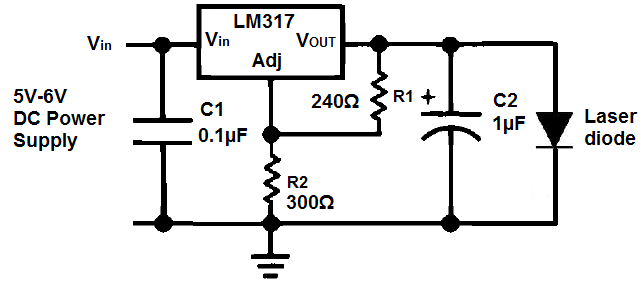
Power Supply is 9vDC @ 200mA (wall adapter) going through a LM317LZ Voltage converter.
C1 is a standard .1uF Ceramic Capacitor
C2 is an 1uF Electrolitic Capacitor
I am going to be using a 5mw 650nm Laser Diode which operates at 2.4v-2.6v.
There will also be a push button on/off switch in line somewhere as the unit only needs to come on occasionally.

What I NEED to know is the values of the two resistors (R1 and R2), plus any other pointers any of you may have for me :)

Thanks!!!
-Pastor Gordon
 
Last edited:


Joined
Nov 1, 2014
Messages
662
Points
28
Dont use lm317 as a voltage regulator, use it as a current regulator. Use this to find out the resistor needed
 
Last edited:
Joined
May 14, 2013
Messages
3,438
Points
0
I make my own colloidal silver. I advise against a 650nm. Use a 635nm that is 4.9 - 5mW. I just use a pen type laser that runs on 2 AAA batteries but I've been wanting to replace it with a lab laser that plugs into the wall.

Alan
 
Joined
Jun 4, 2015
Messages
11
Points
0
I make my own colloidal silver. I advise against a 650nm. Use a 635nm that is 4.9 - 5mW. I just use a pen type laser that runs on 2 AAA batteries but I've been wanting to replace it with a lab laser that plugs into the wall.

Alan

The 650 is what I have available... And I have also been using a pen laser for years to shine through the jar. However, I want this setup to have a laser built into it, so all you have to do is push the button and a laser shines down in the jar, rather than looking through every junk drawer in the house for a laser pen. The CS generator itself will be installed into a very small project box that attaches to the lid of a mason jar... I'm using the pulse generator model to produce nano particles of silver... A Laser driver could easily be added to the small circuit board of the pulse generator. This is what I am trying to do ... I'm just not sure about driving lasers...
 
Joined
May 14, 2013
Messages
3,438
Points
0
That sounds like a great idea, I have yet to see one with the laser built in.

Alan
 
Joined
Jun 4, 2015
Messages
11
Points
0
Dont use lm317 as a voltage regulator, use it as a current regulator. Use this to find out the resistor needed

When I click that link, it shows me a diagram with only the lm317 and 1 resistor for the output. Everywhere I read it says that I need a driver. But from the diagram in that link it does not have the 2 capacitors, or one of the other resistors.

I need a power output between 2.4 and 2.6 volts.
Here is the actual diode...
As you can see it does not have a driver at all. Are you telling me that I don't need one? Or what?

480x480-10358.Jpg
 

diachi

0
Joined
Feb 22, 2008
Messages
9,700
Points
113
When I click that link, it shows me a diagram with only the lm317 and 1 resistor for the output. Everywhere I read it says that I need a driver. But from the diagram in that link it does not have the 2 capacitors, or one of the other resistors.

I need a power output between 2.4 and 2.6 volts.
Here is the actual diode...
As you can see it does not have a driver at all. Are you telling me that I don't need one? Or what?

480x480-10358.Jpg

That's just a very basic schematic to give a basic idea of how it should be set up.

11711-diy-homemade-laser-diode-driver-lm317_components01_001.jpg


This does the same thing, but the above design will provide some protection for your diode. The above schematic allows for adjustable current, you can replace the two resistors and the variable resistor with one resistor the value of which would be calculated from the link marcuspeh posted in order to achieve a fixed current. Diodes don't have drivers built in, you will need to build one as per the schematic I posted.
 
Last edited:
Joined
Jun 4, 2015
Messages
11
Points
0
That's just a very basic schematic to give a basic idea of how it should be set up.

11711-diy-homemade-laser-diode-driver-lm317_components01_001.jpg


This does the same thing, but the above design will provide some protection for your diode. The above schematic allows for adjustable current, you can replace the two resistors and the variable resistor with one resistor the value of which would be calculated from the link marcuspeh posted in order to achieve a fixed current. Diodes don't have drivers built in, you will need to build one as per the schematic I posted.

Ok, I think I understand... but I am HORRIBLE with math lol. Can you please tell me what resistor to use? Provided that the laser diode is 5MW 650NM. Using the calculator from that link confuses me because I dont know what "milli-amps" this diode requires... All I know for sure is that it draws between 2.4 and 2.6 volts.
 
Joined
Jun 4, 2015
Messages
11
Points
0
Maybe Id be better off just buying a couple of these and add a buck converter in my box to drop the power from 9v to 3v. I get confused real easy... Im good at following directions though lol.

6008.Jpg
 

diachi

0
Joined
Feb 22, 2008
Messages
9,700
Points
113
Ok, I think I understand... but I am HORRIBLE with math lol. Can you please tell me what resistor to use? Provided that the laser diode is 5MW 650NM. Using the calculator from that link confuses me because I dont know what "milli-amps" this diode requires... All I know for sure is that it draws between 2.4 and 2.6 volts.

You'd need to post a link to the diode in question, no way to know what the current is supposed to be otherwise.

You could use those ready built modules that have the driver already built in, and then use an LM317 or other linear voltage regulator to drive it. A little less efficient, but at those powers it doesn't make much of a difference.


Something like this: 5X 5mW 650nm RED Laser DOT Module FOR Party Lightshow | eBay

All you need then is an LM7805 to drop your 9V down to 5V.


Edit: My bad, those are 3-4.5V - You'd need an LM7805 and a 1N4001 rectifier diode to bring the voltage down to ~4.3V. There are 5V modules available on eBay too though.
 
Last edited:
Joined
Jun 4, 2015
Messages
11
Points
0
THIS is the diode I am wanting to use... But I have to build a driver for it. Its a LiteOn #LTLD505T laser diode. There is a spec sheet available on the page I linked too...

With the way I am designing this box, it would be easier for me to add the diode and the driver circuit on the same board as the CS generator circuit.
 

Gadget

0
Joined
Dec 28, 2013
Messages
358
Points
43
You'd need 27.78Ω to get .045 amps, which is the Typical Operating Current of your diode.

The caps aren't shown in any sense resistor calculator that I know of, but you do need to put them in.
You can use the LM317 based driver circuit that diachi posted, but use a single resistor instead of the
two resistors and potentiometer. The closer you get the input voltage to the total of the LM317 (~1.25v) + diode (~2.5v) voltage drop, the
less heat you'll have to dissipate on the 317. Even at 9v, the 317 will need a heatsink. 5v would be better heat-wise.

-G
 
Last edited:
Joined
Sep 12, 2007
Messages
9,399
Points
113
Oh come on your guys, this is goofy.

Use a resistive dropper (like you would an LED) of about 150ohms and stick it right on the 9V supply. The 9V is constant, so the current to the diode will also be constant. It's literally exactly as efficient, and uses one part.
 

anderp

0
Joined
May 17, 2015
Messages
27
Points
3
That only works if you trust the power supply to be stable, though. If it's a cheap chinese switchmode brick...
 

diachi

0
Joined
Feb 22, 2008
Messages
9,700
Points
113
That only works if you trust the power supply to be stable, though. If it's a cheap chinese switchmode brick...


You took the words right out of my mouth. Even wall warts don't necessarily have the cleanest power - sometimes they are a couple of volts higher than rated until you put some load on them.
 
Joined
Jun 4, 2015
Messages
11
Points
0
You took the words right out of my mouth. Even wall warts don't necessarily have the cleanest power - sometimes they are a couple of volts higher than rated until you put some load on them.

Must also keep in mind that the same 9v power supply is feeding the CS Generator Circuit... It is based off of the schematic pictured below, only there is a 1k ohm resistor on the output to the anode instead of a 75 ohm, and there is no meter,and Im using a 9v power supply instead of the 12-18... If it wont work with the 9v then Ill have to switch to a 12, so I need a steady source for the laser diode no matter what power supply is used...

diagrm2.jpg


Top