- Joined
- Aug 26, 2009
- Messages
- 186
- Points
- 0
Well, with this whole 445nm fever going on, and red is still a beautiful color. I really can't resist stopping and looking at these pics. Really good, by the way.
Nice build !
Nice build !


Sad news.... RIP 24X diode. Gone. Dead. Kaput. I suspect I killed it by driving it with a STUPID little multi-select transformer power supply. I'm angry with myself... this is a crappy non-regulated power supply. I'm certain that's what did it, a spike from that. I'm still grieving the loss of my baby... :cryyy:
I'm going to try again. The project was so successful up to this point. I'm SURE I had adequate thermal contact, enough heat sinking and was driving it at a conservative current... the only explanation is a voltage spike from the transformer... (?)
")
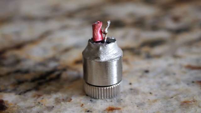
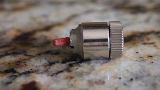
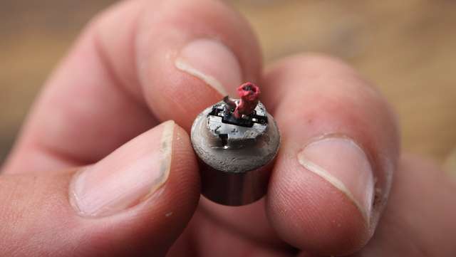
There seems to be a trend, and it's not good for us DIYers.. manufacturers are making it harder to extract these diodes. It used to be most of these sleds had closed can diodes that were press-fit into a heatsink. They could usually be easily be extracted. Now more and more of the diodes are 'open can' (saves cost, but not good for DIY builds.. you don't want dust accumulating on the facets of the diode IMO) and are housed in armor-like heatsinks, making extraction much more difficult.