Welcome to Laser Pointer Forums - discuss green laser pointers, blue laser pointers, and all types of lasers

LPF Donation via Stripe | LPF Donation - Other Methods

Links below open in new window

ArcticMyst Security by Avery

Mitsubishi ML520G71 635nm focussing issue

Joined
Nov 7, 2013
Messages
39
Points
0
Hello there,

Problem:
I bought a Mitsubishi ML520G71 laser diode (red-orange 635nm; 300mW) but I can't seem to focus the beam to a small dot.

I am aware that it's normal for the laser pattern to be a line. However it should be possible to make this line-shape very small right? (let's say at least 6mm diameter)

Lens:
The lens I'm using is one of the standard aixiz modules, and it Does work on my other diodes. I'm also sure that it's not inserted backwards.

Explanation:
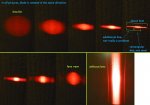
I added a picture where I changed the distance of the lens in a few steps, so that you can see what is happening. The last picture shows the laser pattern without lens.

The line which you see in the picture (picture indicated with "smallest possible"), is NOT the line of the laser line pattern, but comes from somewhere else. I know this because the line I'm seeing is perpendicular to the diode's line pattern.
So where did the line from the laser pattern go? Well, that one is focused into some kind of rectangular-ish dot, as you can clearly see in the 7th picture. In picture 5, that rectangle is as flat as possible, but it's width is sadly still the same.

If the line was just additional, apart from the dot itself, it would not be a problem. But the dot itself is also line-shaped in the same direction (so also perpendicular to the diode's line pattern)

When looking at the beam outside, in foggy sky:
When holding the diode's line pattern horizontal (meaning the strange output line is vertical), the laser beam looks really narrow, just like how I want it. This, because I'm looking from the top onto the beam, so no matter how wide the beam is in the vertical direction, when looking at it from the top, it'll always look small.

When holding the diode's line pattern vertical (meaning the outputted like is horizontal), the laser beam looks small close to the origin, but when going a few meters further, you can see the beam diverging terribly.

This test was helpful to tell if the line which I saw on the wall, was just a dull line, or a bright beam of light. Sadly it was the second because it was Really visible in the fog.


How is this possible? Why can't I focus the line into a very small line?

Kind regards!
 

Attachments

  • P1020522--.jpg
    P1020522--.jpg
    143.1 KB · Views: 3,299


Joined
Feb 4, 2010
Messages
3,280
Points
113
The top right spot is the best one you're going to get with standard lenses.

You can always get a FAC (fast axis collimating) lens
 
Last edited:
Joined
Feb 4, 2010
Messages
3,280
Points
113
It's just like how other lasers' spots at long distances are much larger than they are at the laser aperture, it's due to the divergence.

In most diodes, there are two divergence axes. The "slow axis" and the "fast axis".

Unfortunately, the rate at which the fast axis diverges is often many multiples higher than that of the slow axis. Meaning it may start out the same shape, but eventually the one axis is going to get brutally stretched.

You can focus it so that the fast axis's divergence is much lower with FAC lenses (fast-axis collimating)
Note your beam will still be rectangular in shape.

I'm not the best in terms of building lasers so someone else can take over who can better explain what to do with the FAC lens.
 
Last edited:
Joined
Feb 25, 2010
Messages
1,643
Points
113
The Mits P73 and G71 were a major interest of mine over at PL !!

Mitsubishi ML520G71...Red Holy Grail or Flashlight Fail ?? - Page 55

This thread is 55 pages long and contains 1359 posts. It outlines the entire history of how we eventually tamed the slow axis astigmatism ( Beam Spread )

This is a difficult thread to read....for many,many minds....with much,much greater knowledge in optics then I have ...moved this project along....BUT...ALL is explained here !!!!!

The bottom line is that this diode CAN be corrected. It COULD even be corrected in the Hand Held format !!!!!!!!!!!!!!!! BUT...NOT easy !!!...not too small...and $$$

It is difficult to correct it...even in a projector...with plenty of room !!!....But...it was corrected !!!

CDBEAM=======>
 
Last edited:
Joined
Aug 14, 2013
Messages
2,655
Points
63
This cannot be corrected with a FAC without decanning the diode. It either requires a prism pair or I guess
the cylinder lens pair CDBEAM mentioned. That is a new one to me.
 

NKO29

0
Joined
Jun 6, 2013
Messages
861
Points
28
Whoa a 3cm "smallest" dot, thats a bit big isnt it? Otherwise that shape is normal :)
I'm no expert on optics thats all i had to say hahaha :)
-Josh
 
Joined
Nov 7, 2013
Messages
39
Points
0
Thanks for all the replies! this explains a lot.
So basically I just bought a wrong diode.. I never wanted this :S

How can I know this in the future? How can I see if a diode will be "unfocussable" like this?
is it the "far field patterns" graphic in the datasheet page 3? Because both graphs differ so much?

And here something I just thought about, but probably will not work:
What if I focus the light into a line pattern, like in the topright picture that I posted,
and then after that, use a lens which is parabolic in just one axis, to focus that line into a dot?
(regular lenses are parabolic in a circular way; in all directions, but won't there exist lenses which are just parabolic in one direction, and flat in the other way?)


Whoa a 3cm "smallest" dot, thats a bit big isnt it? Otherwise that shape is normal :)
I'm no expert on optics thats all i had to say hahaha :)
-Josh
And that 3cm is at a distance of only 1.2m :p if I shine it across my room, it gets 10cm long. When shining it outside it simply looks terrible :(
 
Last edited:
Joined
Aug 14, 2013
Messages
2,655
Points
63
Thanks for all the replies! this explains a lot.
So basically I just bought a wrong diode.. I never wanted this :S

How can I know this in the future? How can I see if a diode will be "unfocussable" like this?
is it the "far field patterns" graphic in the datasheet page 3? Because both graphs differ so much?

You're looking for weather the diode is single mode or multimode. Multimode diodes will
always display this characteristic (unless they have a FAC). That far field graph will clue
you in as well. The red curve is the fast axis and the pink curve is the slow.

And here something I just thought about, but probably will not work:
What if I focus the light into a line pattern, like in the topright picture that I posted,
and then after that, use a lens which is parabolic in just one axis, to focus that line into a dot?
(regular lenses are parabolic in a circular way; in all directions, but won't there exist lenses which are just parabolic in one direction, and flat in the other way?)

Yes, you are describing the cylinder lenses we are discussing. Go and read that thread
CDBEAM linked to.
 
Joined
Nov 7, 2013
Messages
39
Points
0
Alright, thanks! I learned a lot from this ^^

Another question:
What do you think the limit of this diode would be?
I'm quite new to lasers, and very unsure when it comes to trying out what I can get from a diode.

In the datasheet, the maximum current is stated 400mA, which is also the current at which I'm running it right now. However, I read this diode can handle more?

I suppose it depends on how good your cooling is? In that case, I'll explain you how it's like in my build:
I have inserted the diode into a standard aixiz module. That module is placed in a heatsink which originally was used for a TO220 package, but I drilled a hole in it for the laser module. The heatsink is about 4x3x1cm.

I read on these forums that it could go up to 750mA?
Would the diode survive up to 1A? And are there any signs the diode gives when I reach it's limit?

Oh, one more thing: the pattern I'm seeing when using no lens, it's all nice lines which don't change in size, only in intensity; like it should be.
But for some reason, the lines suddenly 'pop' into a different line pattern when I go from below ~390mA to above ~390mA. After that, when going up to 400mA, the pattern is again not changing anymore.
Why does this happen? Is it bad?
 
Last edited:

Blord

0
Joined
Dec 24, 2007
Messages
5,356
Points
0
If you want a single mode 638nm laser I would suggest the Opnext 120mW laserdiode HL63603TG. It gives no pattern when the lens is removed. Just a red splash. See the picture of the unfocussed dot. This diode can be pushed to give 200mW output.

Ehgemus_15270_12.jpg
 
Joined
Jun 25, 2011
Messages
1,481
Points
63
just what lens are you using? it's possible you are not getting the lens close enough to the diode. i was able to focus my diode's output to a(n) (apparent) pinpoint a close distance ~2m using the 3 element aixiz or g1 lens. i never liked this diode and do not even own one now. it makes our mm 445's look single mode
 
Last edited:
Joined
Nov 7, 2013
Messages
39
Points
0
@blord: 200mW won't be enough. I want to make a laser that has a visible beam in daylight conditions. The diode I'm using now is getting very close to my satisfaction but I'd like to get some more out of it.

@cheech226: I'm using the standard lens that came with the aixiz module. I'm quite sure that the lens Does get close enough, because there is a certain point at which the dot is as small as possible, and then after that it diverges again. (as you can see in the pictures in post#1).


BTW, the laser I've built is the one from my display picture ^^ There you can also see the heatsink.
 
Last edited:


Top