Welcome to Laser Pointer Forums - discuss green laser pointers, blue laser pointers, and all types of lasers

LPF Donation via Stripe | LPF Donation - Other Methods

Links below open in new window

ArcticMyst Security by Avery

My Star Trek Phaser Mod

Joined
Jul 24, 2007
Messages
2,749
Points
0
are you referring to two or more cables simply being "bunched" together?
I am not sure how it was done to be honest, I assumed that they were spliced in some way to give a single strand output as that would be ultimately the best way.
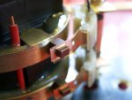
Your rotating caps are they to be coupled by slip rings and brushes? something like this......

Regards rog8811
 

Attachments

  • brushes fitted01.jpg
    brushes fitted01.jpg
    79.1 KB · Views: 447


Joined
Jun 7, 2009
Messages
118
Points
0
So If I wanted the laser to continue to operate at its RATED power (and not burn it out) Id need to use a driver circuit right?

Id like to do this with the Blue Ray diode. Would a 9 v battery be too much power? What would you need to do to put the Blue Ray diode (Or hell even green) into the phaser, and make it work at a safe power level so it lasts as long as its supposed to?

So far from what I understand its as simple as..

1. Buy Diode

2. Buy laser module and insert diode/replace diode

3. Buy driver circuit and connect the power leads to the driver circuit, and output leads from Driver circuit to diode.

But what power source should be used? Theres supposed to be a potentiometer on the driver circuit right? So you could tune it down to reduce the lasers power..but what about burning up the driver circuit with a 9 v battery..is that too much? Would Double AA's be too little?

I know you can adjust the lasers power via your "knob" on the laser..but what about current spikes?
 
Last edited:
Joined
Mar 10, 2009
Messages
878
Points
0
Connect the pin of the diode to the case case pin (not used). Then can solder the positive wire of the driver to the metal tab easly, or try to install a spring, but the first methode is the simples. You want to create a module somewhat like the one he used, but without a PCB sticking out. There's some batteries that exist that are identical in dimension as AAs, but 3.7v, use two.
 
Joined
Jun 7, 2009
Messages
118
Points
0
Im a complete noob..so thats not helpful. Are you saying 3.7v is what would normally run a Blu-Ray diode?

What im saying is..Id need to find out the rated max power of whatever Diode i use right? So if its a blu ray diode..and it says on the specs its 100mA at say..5V..Id need to check the driver circuit to make sure its outputing 100mA and 5 volts right? that way the diode is operating as it was designed

Then it would be good to go?

I dont just want to plug it all up and it shines...then breaks because of a current spike or because its running at too much power..or have it running at not enough power to burn stuff.

Should I get like a Volt meter? Then test my power sources coming out of the driver circuit itself? To make sure its right? Then I could just tune the Pot untill the volt meter shows its within the Diodes "happy place" right?
 
Last edited:
Joined
Mar 10, 2009
Messages
878
Points
0
You gotta get a driver circuit. Or you get a Rkcstr or a flexdrive. Assemble the laser module like you see on tutorials in the tut section.
 
Joined
Jun 7, 2009
Messages
118
Points
0
I see now..I watched a video on building a driver circuit. Apparantly you just star with the pot at max resistance..then turn it until the laser shines..as soon as it shines I guess this is the current its SUPPOSED to be at..So then its good ^_^ Ill try building my ow ndriver circuit now :)
 
Joined
Mar 10, 2009
Messages
878
Points
0
Nooo!!!

You neeed a dummy load!!

You cannot estiamate mA by loooing at you diode!!!

Please, please, go read info in the tutorial section!!
 
Joined
Jun 7, 2009
Messages
118
Points
0
Rog,

thanks for the kind welcome. Yes, it's been my only build so far. I am working part-time on a 7 laser assault rifle but the alignment of the beams into a 6mm perfectly parallel energy stream is giving me a real headache. The mirrors required to align the 7 lasers are ridiculously expensive and outside my means. Alker, the fiber optics people (they do all the fiber optics for the Eurofigher jet) are helping me with the problem and are trying to find the right optic for the nanometerage of the diode (532nm) and once they find a cable that will allow the transfer of the beam in a clearly visible stream once it leaves the end of the cable then I am up and running. A lot has to do with the last 100mm of the 7 optic cables being perfectly parallel and the finish of the 1.5mm cables end. It has to be lensed to a precise curveture or the beam will spread rather than remain collimated.

The sale of the Phaser will help to go towards development and component costs.

depth3d


Im confused. By combining the beams are you intending to multiply its burning power?

Wont the beams only "converge" at a certain range though? no matter how you align them? Too close to the target and the beams wont converge anyway...too far and the beams will cross their apex right? Or is that the point of the fiber optics? Are you converging the beams inside the "rifle" and collimating all of them together into a single beam before it leaves the gun?

Sounds so interesting!!! ^_^
 
Joined
Jun 7, 2009
Messages
118
Points
0
Like im going to make a new thread to discuss this when it has already been introduced by someone else in the thread?
 

Switch

0
Joined
Dec 9, 2007
Messages
3,327
Points
0
He wants the beams to be parallel not really combine them.He also wants recollimation by shaping the end of the fiber optic like a lens instead of adding an additional lens, which is probably gonna minimize power loss too. Btw I think that by "converge" you want to say "intersect".

Btw, depth3d, that gun completely kicks ass!! Just a few questions:

What power will the lasers be?
Do you really need capacitors to fire them?

Also , it looks as if there isn't enough space for your thumb behind the gun grip.
 
Last edited:
Joined
Jun 6, 2009
Messages
18
Points
0
Kick ass assault rifle

Switch

It's dudes like you that inspire dudes like me to great things. Thanks for all the comments, mate.

Yes, you are spot on. I want to align the beams rather than combine them. that way I can modulate the firing sequences to give varying patterns relative to the blast mode; pulse, chain etc.

I will be using 240mW diodes if I can find a reliable breed that will last a little longer than five minutes. I am not interested in achieving burning lasers, more interested in visibility. The capacitors I mentioned in the Capacitor Rotor Bolts (CRB's) are purely for effect only. I wanted to give the rifle some life so that every time the trigger was pulled, you would see some outward sign of the mechanics behind the laser blast that ensued. I put the original text explaining their function in italics but it wasn't really clever enough to put across that they were not a part of the laser process, just to indicate something else happening along the way to blasting the bad guys. The CRB's action will be handled by a servo with a sprung loaded clutch so that if the rotation of the bolts and backplate is interfered with manually, the bolts will simply stop against the pressure without overstressing the servo.

The only other capacitors in the weapon will be housed in the diode array block as a safely measure against anyone trying to ramp up the power to burning levels. Anyone trying to get inside the array will have to know the sequential method for disassembly or any one of the three microswitches will trigger a massive charge from the capacitor into the diodes and PCB drivers frying them completely.


You were quite right about the space behind the trigger guard. The trigger mechanism was purely indicative. I just whopped any ol' thing in there to fill in the space as I hadn't got around to designing that bit of the rifle as yet.

Any suggestions you might have I'll be happy to hear about. Good to find someone who knows their stuff.

depth3d
 

Switch

0
Joined
Dec 9, 2007
Messages
3,327
Points
0
Well I guess I misread your post about the capacitors. That sounds really cool.It looks like the gun will be a pleasure to fire. Also 240mW sounds enough to have some fun shooting balloons lol :D For maximum visibility you should go for green, but 240mW modules are pretty expensive(not really something you want to have an autodestruct sequence for lol) and I have no idea how you would go about fiber coupling those.They'll also be so damn bright , and 6 of them...you'd just NEED goggles unless you fire that thing in the sky.

The way you're probably gonna fire it, it looks like you won't need extended duty cycles so that's good cause you don't need a lot of cooling for the lasers.

Please post a picture if you do any further modifications to the design :)
 

HIMNL9

0
Joined
May 26, 2009
Messages
5,318
Points
0
About combining fibers, there's already a lot of these applications, from simple 2-to-1 combiners, to multiple chips fiber-coupled single output modules.

I've seen them lots of times randomly appears on ebay, too ..... one was coupling 30 standard cans half watt 808nm diodes plus one red diode in a single-output 15W 808nm module, and the red diode was just used as "pointer" for focus the beam on the target ..... usually, instead, they couple bare chips or c-mount emitters, but the principle is the same.


Top