

LazyBeam
0
- Joined
- Jun 12, 2010
- Messages
- 462
- Points
- 28
Ok, so it seems like I've taken forever to finish this... but since it was my first build I took it slow.
It's a pretty straight forward build with the SF-AW210 diode and flexdrive. I just added a little twist to be unique.
For anyone wondering... yes I destroyed my first LD harvesting it. Good thing I got 3 sleds
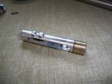
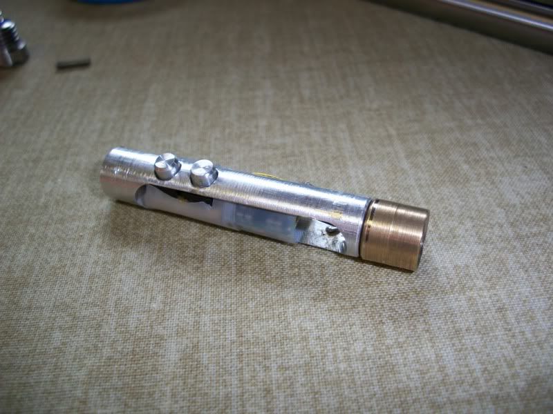
The SF-AW210 LD is seated in an Aixiz module that was turned down to 10.1mm and has a press fit step machined in the back. The back half of the module got pitched in the trash. The modified aixiz head presses into an aluminum sled that holds the Flexdrive, power board and the negative terminal (the host is case positive).
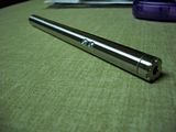
The host body is 12.5mm in OD and the front ID is 10.2mm and the rear ID (batteries) is 10.5mm. Unfortunately the body is a little tight on triple A batteries and the only AAA I get to freely slide in & out are Duracell alkaline... but they seem to work fine. The host body & battery cap are all 18-8 stainless and the buttons & sled are 6061 aluminum. The sled uses two M2.5x0.45 screws to stay secured in the host body. Even though the body is case positive, the battery spring is on the tail cap because it was easiest to do this way. I still need to attach the custom focusing to the body so that screwed all the way it's focused to "infinity". There's also still one or two machine marks I need to brush out of the body from some touch up machine work.
A custom power board (push-button switches, resistors, and hobby board) is interfaced to the backside of the flexdrive and set to supply either 65mA or 165mA. With aixiz 405 glass this should be around 40mW and 180mW. It's a tight fit so I had to use clear tape to insulate the electronics. I have pics of the power board and driver... but I misplaced them at the moment (remember when HDDs were only 100MB? lol). I'm still debating whether or not to coat the back of the LD in thermal adhesive. As it is now, it can be disassembled to fix any future problems.
When I figure out how to do a proper beamshot (safely) I'll post a video. The camera won't pick up the visible beam.
The clicking noise in the video is the crappy camera focusing mechanism...
Video: http://www.youtube.com/watch?v=W3fiLxBPb58


It's a pretty straight forward build with the SF-AW210 diode and flexdrive. I just added a little twist to be unique.
For anyone wondering... yes I destroyed my first LD harvesting it. Good thing I got 3 sleds
The SF-AW210 LD is seated in an Aixiz module that was turned down to 10.1mm and has a press fit step machined in the back. The back half of the module got pitched in the trash. The modified aixiz head presses into an aluminum sled that holds the Flexdrive, power board and the negative terminal (the host is case positive).
The host body is 12.5mm in OD and the front ID is 10.2mm and the rear ID (batteries) is 10.5mm. Unfortunately the body is a little tight on triple A batteries and the only AAA I get to freely slide in & out are Duracell alkaline... but they seem to work fine. The host body & battery cap are all 18-8 stainless and the buttons & sled are 6061 aluminum. The sled uses two M2.5x0.45 screws to stay secured in the host body. Even though the body is case positive, the battery spring is on the tail cap because it was easiest to do this way. I still need to attach the custom focusing to the body so that screwed all the way it's focused to "infinity". There's also still one or two machine marks I need to brush out of the body from some touch up machine work.
A custom power board (push-button switches, resistors, and hobby board) is interfaced to the backside of the flexdrive and set to supply either 65mA or 165mA. With aixiz 405 glass this should be around 40mW and 180mW. It's a tight fit so I had to use clear tape to insulate the electronics. I have pics of the power board and driver... but I misplaced them at the moment (remember when HDDs were only 100MB? lol). I'm still debating whether or not to coat the back of the LD in thermal adhesive. As it is now, it can be disassembled to fix any future problems.
When I figure out how to do a proper beamshot (safely) I'll post a video. The camera won't pick up the visible beam.
The clicking noise in the video is the crappy camera focusing mechanism...
Video: http://www.youtube.com/watch?v=W3fiLxBPb58


Last edited:


")