Welcome to Laser Pointer Forums - discuss green laser pointers, blue laser pointers, and all types of lasers

Buy Site Supporter Role (remove some ads) | LPF Donations

Links below open in new window

FrozenGate by Avery

Scanner opinions

Joined
Nov 12, 2009
Messages
222
Points
0
Can I get some opinions on my choice of components for a scanner.


Laser scanner equipment

This is a DIY project on a reasonable budget $600-$700. I've read most of the threads about setting these up. Looks like a fun challenge. At $570 atm


Scanner
30Kpps Laser galvo Scanner (30,000 points p/sec) ILDA - Ordered $157.50


Software

Spaghetti($50) - purchased


DAC
DrLava's LaserBoy Correction Amp ($40) Ordered + built
DX usb soundcard(18.50) - ordered - built and tuned


Lasers - I want analog control.

Green - Aixiz 50mW module + DrLava's FlexMod($30) - Assembled
Red - Diode from LPC-815 + DrLava's FlexMod ($30) - Assembled
Violet - GGW-H20L + 405-g-1(Ordered) + DrLava's FlexMod ($30) - Assembling

Assorted Dichro's and mirrrors

Dichro's scavanged from LCD projector - Done
Dichro and mirror mounts - handmade - was fun to design and build them.

Heatsinks for the Violet and Red - Done
I'm figuring 50mW green, 150mW red, 200 mW Violet

My house has a perfect 15' x 15' wall opposite a raised dining room, so I can set the scanner up so the beams are well above ppl's heads.
 
Last edited:


Re: Scanner opinoins

Don't pay >$300 for 20k scanners. Here's some links for as little as $110 + shipping. These days it seems like there's little difference between Chinese scanners.

SCANLSP-20 20k Scanner Laser Show Galvo for DPSS Argon - eBay (item 350262590543 end time Oct-29-09 12:51:31 PDT)

30Kpps Laser galvo Scanner (30,000 points p/sec) ILDA - eBay (item 300358493024 end time Dec-17-09 01:41:13 PST)

laser show galvo scanner CW20K Scanning galvanometer - eBay (item 120483974242 end time Dec-21-09 18:11:56 PST)


You can use a flexmod with any lab-style system as long as you know roughly what the diode current should be.

The rest of the stuff sounds good. You can theoretically use any 5.1 channel (or better) sound card for the DAC, so your sound blaster should work fine. If you need a tutorial on building a sound card DAC, there is one here: http://laserpointerforums.com/f47/sound-card-dac-tutorial-40569.html
 
Re: Scanner opinoins

I'd recommend going straight to 30K scanners. You will run into a lot of frames intended for 30K scanners and you will wish you had them. You can get a 30K set for under $300 now. Last I checked the Z30s were under $250 from LaserPic.

I have a Black Friday sale going on for Spaghetti. It's $35 if you send me an email on Nov 27 and send payment within 5 days. I will be raising the price to $75 after the new year most likely.

I have a 50mw green in my scanner and it works pretty good if you use it in a garage or something like that. I have a 200mw red that I made out of a DVD diode and a 50mw 473nm blue. 150mw for you red seems a little weak since you can easily get 250mw from an open can diode. I have no idea how much power you need with the 405nm blu-ray but I would like to hear how much is required to make white with your setup since I would like to do the same.
 
Last edited:
Re: Scanner opinoins

Thanks for the links, I saw the Scanlsp's, but the other 2 escaped my searches.

The 30k looks like a good deal.

Quick question on the DAC tutorial. You say to connect to the positive side of the output cap, is this because we want the sound signal still riding on the DC carrier? If so, I could theoretically take the output from the audio jacks and run the signals through another circuit to add them back to a carrier.


I will definitely take your black friday deal, Gary.

I based my power ratio's on the ones Andy has on his site.

2-1 red to green, 3-1 blue to green. I think his red is 635, so may need more for 650( or whatever the lpc diode is). His blue ratio is for 473, so I figured I would need at least 4-1( maybe 5-1) for 405.


Thanks for the responses.:thanks:
 
Re: Scanner opinoins

Quick question on the DAC tutorial. You say to connect to the positive side of the output cap, is this because we want the sound signal still riding on the DC carrier? If so, I could theoretically take the output from the audio jacks and run the signals through another circuit to add them back to a carrier.

That's exactly right. You can do as you theoretically suggest, but it might be more complicated than just tapping the positive side of the caps. It's really up to you.
 
Probably have to go the USB soundcard route, the Audigy has 50+ electrolytic Caps and 100+ smd Caps. Trying to trace the Outputs back to one single cap is more than my eyes can handle.
 
Re: Scanner opinoins

Think I better just point this out! The scanners pictured in that ad are actually the 20k scanners we sell, not the 30k scanners! Pretty cheeky!

Ya, found that out too late. Will do 30k at 8° though. Don't need more than that for my needs. Was still the best price I could find(they have bumped the price up $20 since I bought).
 
They are 20k scanners. They come close to 30k ( 25-27k ), but they are most certainly not 30k scanners!
 
Question for dave_LSP, the input cables for the scanner amps have 3 connections (in+, in-, gnd.), the ILDA connector doesn't have a ground for the scanner signal (only X+, X-).

Should I connect the ground to system ground, or leave unconnected?

The is my design
Untitled-1.jpg
 
Last edited:
Where I am so far


No lasers connected right now, LPC died, and not happy with the red and violet mounts. Ordered some z-bolt heatsinks to replace. Can't find the mounting screws for the green locally. So need to order.


test pattern using my phr handheld, so no blanking. Obviously needs tuning.
 
Last edited:
Do you have any better pics of your test pattern? Do you have pics of these other ones too?

IMG_2085.JPG


IMG_2086.JPG


(Skewed cos they were scanned at an angle)
 
Actually, the pic is of the ILDA 30k pattern. I'll mount my LCC tomorrow and get some better pics.

I was trying to hold my phr aimed at the scanner head and use the camera at the same time. fail.:(

I haven't done any tuning yet, I just hooked it up to check the connections and the DAC. It was supposedly tuned for 20k at 20° at the factory. I was only running it at 16k for the test, so I didn't expect the pattern to look good.

I found out the you need to follow drlava's instructions for tuning the flexmods exactly!. Instead of tuning with a dmm connected to the output, I tried to tune with a dummy load. I set the current for 350ma for my LOC with the dummy load. Unfortunately, when connected to the ld the current was over 600ma, the max for the low range. Oh well, live and learn. Luckily I've got the LCC from the GGW sled.
 
Last edited:
This is what I'm getting now, just a constantly changing swirl of lines. I think I need to retune the DAC, as I am also not getting any modulation to my red. I took this using my handheld green.


X output from DAC 1v/div


Y output from DAC 1v/div


Red modulation from DAC 1v/div
 
Last edited:
OK, solved that problem, seems the db25 cable I was using is bad. DB25 connector on dac directly to breakout board now.

100_0394.jpg


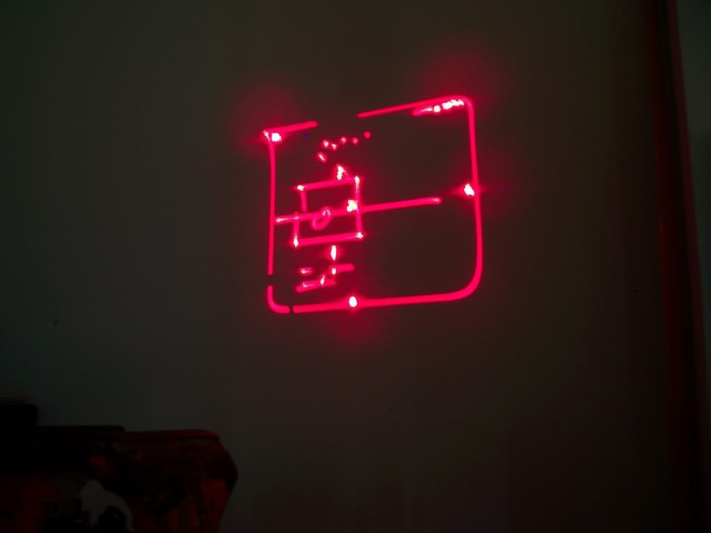
Still looks like crap, but at least its a pattern. Blanking on the red is also working.

actual pattern is about 9"x9" over a 17.5' distance. A scan angle of only 2.5 degrees. Which seems to be maxed out. (Maybe I need to change the DC-DC converter ElectroFreak mentioned.)

I tried the pattern with Spaghetti and LFI, both produce the same results.

Edit: changed output to monochrone, some lines were missing as I only had 1 laser connected.
 
Last edited:


Back
Top