Welcome to Laser Pointer Forums - discuss green laser pointers, blue laser pointers, and all types of lasers

LPF Donation via Stripe | LPF Donation - Other Methods

Links below open in new window

ArcticMyst Security by Avery

New scanning motors?

Joined
Oct 24, 2009
Messages
2,555
Points
48
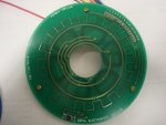
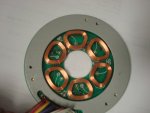
i found this when looking for scanner motors.
COPAL POLYGON MIRROR LASER SCANNER - Surplus Shed
I see its used for scanning in medical equipment my question is what type of motor is that? stepper, servo.
Can these be used to make a laser scanner?
Depending on the type of motor how do you drive them?

(i searched the forums and got someone with a post but no details were given on how they worked. Google turned up empty.)

They must be Stepper motors right?
16 leads...
 
Last edited:


Joined
Nov 7, 2008
Messages
5,725
Points
0
Those are just a multi-sided mirror that spins on a pretty much standard motor.. A laser beam projected onto it forms a straight line. That's all they'll do. They come from laser printers and copies.
 
Joined
Oct 24, 2009
Messages
2,555
Points
48
hm. I would think with that many leads it could be used to do more than just spin but thanks.
 
Joined
Nov 7, 2008
Messages
5,725
Points
0
The extra leads are for precisely controlling the motor's speed and monitoring it's behavior.
 

Things

0
Joined
May 1, 2007
Messages
7,517
Points
0
Yeah, they are steppers of a sort, but useless for scanning anything but a line. If you wanted to get tricky, you could set 2 up in an X and Y config and try raster scanning, but that is some very advanced stuff.
 
Joined
Jan 17, 2009
Messages
390
Points
0
If you read it carefully it has something like 6 or 8 mirrors mounted on the shaft and it just spins around really fast. It would make a nice liquid sky effect and you might be able to use it in some kind of raster system if the speed control is precise. For the most part, they aren't worth messing with, though.
 
Joined
Mar 14, 2010
Messages
2
Points
0
Its a 3 pole brushless dc motor.

3 of the wires are for the motor.
The rest are for feedback / motor control.

I have a drawing of the wires if any body is interested.
 
Joined
Oct 24, 2009
Messages
2,555
Points
48
Hm well thanks for the info.
also Welcome to LPF i see this is your first post.
Do you know by owning one or just found documentation?
 
Joined
Mar 14, 2010
Messages
2
Points
0
Were using it in Physics Research.

I own 2 now

I took the first one apart

Heres some PIctures of the inside circuit board

Im building a driver for the motor now. Thats how I came across this web site.

The first pic shows the little black Square thats a hall effect sensor and there is 1 magnet on the bottom of the rotor. im assuming the orginal purpose was for RPM.

The second Picture shows the 3 Hall effect sensors for Phase feedback.

Im Using a LSI/CSI Chip to control it. LS7260 Is the chip number.
 

Attachments

  • DSC03437.JPG
    DSC03437.JPG
    98.1 KB · Views: 220
  • DSC03438.JPG
    DSC03438.JPG
    83.7 KB · Views: 228
Last edited:
Joined
Oct 24, 2009
Messages
2,555
Points
48
wish i knew more... i understand so little still about electronics. i just got the 555 ic down and just got started on pics
 

Things

0
Joined
May 1, 2007
Messages
7,517
Points
0
Driving stepper motors is easy if you used something like a PIC or uC and a transistor array. All you do is switch each coil on and off in sequential order.
 
Joined
Oct 24, 2009
Messages
2,555
Points
48
I know how to drive them i made a controller for my cnc machine. but that was not all on my own power their, but no matter as long as i can learn it and keep my notes i can do it again.
 
Joined
Oct 24, 2009
Messages
2,555
Points
48
Hey dont worry i still know next to nothing i have been trying to build a circuit for weeks now and still cant get it to work right but i am very very close.


Top