hakzaw1
0
- Joined
- Apr 2, 2009
- Messages
- 10,662
- Points
- 113
lately there has been quite a buzz at the show forum concerning both scanners in general but also about some brand new ones that have been reviewed and the results where both surprising and informative to me.-- I have cpoied some from there that I found the most useful and have quite a bit to paste- I will do my best to let you know whose posts I and showing you.
Pangolin, famous for their software has come out with some scanners of their own design- said to perform like Cambridge Tech with a price closer to DTs-
The ones we can afford are mode "SCANNERMAX 506'- and they are 30k- but not at all like any 30K most of us have seen-- I will try place the posts from there in an easy way for reading and posting your comments= but remember these posts are not put here by the authors--so if you have a question for one of those whose work i have copied you need to ask them- and to do that in most cases you will need to go 'over there'..
Much of this comes to us from Bill Benner- he has given me the Ok to start this thread. There is already some scanner info in this section and also at the link in my sig-- thanks to Dan 'Things'
hak
&&&&&&&&&&&&&&&&&&&&&&
Okay-- first I apologize if the order of these 'quotes' is not perfect-
What I had been doing is copypasta interesting posts and replies to them into note- and had to reboot so i just pasted all those into word- I will copy some here in the OP and will let you have some time to read then wil post more- much of this comes from [angolin Bill Benner and involves a new scanner set Pangolin is offering-(the''506' 30k) There is quite a stir about these and two beta testers('Mixed Gas' Steve Roberts and Norty from the UK) & they have a huge review thread going on over 'there' - So to a see a more complete posts in order you are free to lurk on over there- they are open 24/7 .. as usual there the topic strays off with stuff about lenses etc but in some way all is good stuff to know. -- Norty, Bill and Steve have given me the OK to post their stuff .
here-
I know right away some will ask me the prices- so far they have not been given out- I DO know they hope to be priced along the lines of the best from China- and so far that =means its going to be pretty much Dragon Tiger 40K vs Pangolin 506 50K--
Its a long but good read and I feel lucky to have all this given out to read and learn from- scanners are pretty complex and not simple for me to fully understand. --
***************************************************+
long LONG POSTS ON scannermax 506 (Pangolin)
AND SCANNER INFO= FROM PLex
____________________
OO
SCANNERMAX 506
VID
From Bill---in re lenses to make audience scanning safe
**********************************
Hi Keith,
As I said, we actually have a few lenses that do what you need, and do it really well. One of them is being reviewed by AVI right now on a real dome. If we like what we see, then that lens will be a relatively inexpensive option, and one we can deliver within a few weeks. If we think that the divergence increase is too much, then we have an alternative design that we know is super-duper fantastic, but it will take a bit longer to bring to market, because we'll have to develop a lens barrel for it. That means design, machining, etc.
Regarding the scanners themselves, we did our own comparison between Compact 506 and DT40, since that was a topic of discussion on another thread. You can see our video here:
ScannerMAX Compact 506 versus DT40 - YouTube
Bill
_________
Bill,
Thanks a lot for the video. There is so much useful information provided with a video demonstration. For example, the layout of your mounting block is now obvious. Something I have noticed in aligning projectors is the inevitable deterioration of a hard won RGB far field spot to a wider far field line. The scanned line width is never as good as the static beam even when the beam path includes the scanner mirrors ( off, non-scanning). I have always attributed this to a combination of tracking errors and mirror surface distortion under G loading. In both the test patterns and the show the 506 seems to produce sharper lines that are sometimes more obvious and sometimes less. To be fair, do you agree? And if you do, can the effect of the laser sources be isolated to demonstrate this more effectively or predictably?
Larger laser sources (larger beams require larger scanner mirrors) will more likely be used at larger distances and the need for lower divergence will be greater. EMS and Nutfield both changed to fused silica (from what I do not know) to enhance their mirror stiffness ostensibly to allow a thinning (lightening) of their mirrors. What is not discussed is the quantitative effect of mirror stiffness (ie silicon) on the mirror itself. Certainly, if high enough scanning speeds can break a mirror then something short of that has to be undermining a high quality, low divergence laser beam.
*******************
01-21-2014, 17:20 #201 Galvonaut
Senior Member Join Date:Aug 2013
Location:West Sus***
Posts:868
Originally Posted by White-Light
Didn't know you were after a graphics solution Keith.
No worries. Also after beams but don't really require massive angles for them. Some 506s wouldn't go amiss though. Reply Reply With Quote .
--------------------------------------------------------------------------------
01-21-2014, 21:01 #202 Pangolin (Bill)
Senior Member
Join Date:Apr 2006
Location:Orlando, FL - USA
Posts:1,367
Hi Keith,
As I said, we actually have a few lenses that do what you need, and do it really well. One of them is being reviewed by AVI right now on a real dome. If we like what we see, then that lens will be a relatively inexpensive option, and one we can deliver within a few weeks. If we think that the divergence increase is too much, then we have an alternative design that we know is super-duper fantastic, but it will take a bit longer to bring to market, because we'll have to develop a lens barrel for it. That means design, machining, etc.
Regarding the scanners themselves, we did our own comparison between Compact 506 and DT40, since that was a topic of discussion on another thread. You can see our video here:
ScannerMAX Compact 506 versus DT40 - YouTube
Bill Reply Reply With Quote .
--------------------------------------------------------------------------------
01-21-2014, 23:03 #203 Bradfo69
Senior Member Join Date:Jul 2010
Location:Wilmington, DE
Posts:2,757
Nice video Bill. Thank you! Reply Reply With Quote .
--------------------------------------------------------------------------------
Yesterday, 05:56 #204 Galvonaut
Senior Member Join Date:Aug 2013
Location:West Sus***
Posts:868
Originally Posted by Pangolin
Hi Keith,
As I said, we actually have a few lenses that do what you need, and do it really well. One of them is being reviewed by AVI right now on a real dome. If we like what we see, then that lens will be a relatively inexpensive option, and one we can deliver within a few weeks. If we think that the divergence increase is too much, then we have an alternative design that we know is super-duper fantastic, but it will take a bit longer to bring to market, because we'll have to develop a lens barrel for it. That means design, machining, etc.
Regarding the scanners themselves, we did our own comparison between Compact 506 and DT40, since that was a topic of discussion on another thread. You can see our video here:
ScannerMAX Compact 506 versus DT40 - YouTube
Bill
I look forward to hearing more news
Just watched the video on the other thread - Nice results!
Keith Reply Reply With Quote .
--------------------------------------------------------------------------------
Yesterday, 10:51 #205 planters
Senior Member Join Date:Feb 2011
Location:New Hampshire
Posts:1,767
Bill,
Thanks a lot for the video. There is so much useful information provided with a video demonstration. For example, the layout of your mounting block is now obvious. Something I have noticed in aligning projectors is the inevitable deterioration of a hard won RGB far field spot to a wider far field line. The scanned line width is never as good as the static beam even when the beam path includes the scanner mirrors ( off, non-scanning). I have always attributed this to a combination of tracking errors and mirror surface distortion under G loading. In both the test patterns and the show the 506 seems to produce sharper lines that are sometimes more obvious and sometimes less. To be fair, do you agree? And if you do, can the effect of the laser sources be isolated to demonstrate this more effectively or predictably?
Larger laser sources (larger beams require larger scanner mirrors) will more likely be used at larger distances and the need for lower divergence will be greater. EMS and Nutfield both changed to fused silica (from what I do not know) to enhance their mirror stiffness ostensibly to allow a thinning (lightening) of their mirrors. What is not discussed is the quantitative effect of mirror stiffness (ie silicon) on the mirror itself. Certainly, if high enough scanning speeds can break a mirror then something short of that has to be undermining a high quality, low divergence laser beam. Reply Reply With Quote .
--------------------------------------------------------------------------------
Yesterday, 11:24 #206 mixedgas
Infinitus Excellentia Ion Laser Dominatus Join Date:May 2007.
Posts:7,144
Location:A lab with some dripping water on the floor
Mirror photo this afternoon before I ship the system back. You WILL be impressed.
Steve Kyrie Eleison! Reply Reply With Quote .
--------------------------------------------------------------------------------
Yesterday, 12:41 #207 Pangolin
Senior Member
Join Date:Apr 2006
Location:Orlando, FL - USA
Posts:1,367
Originally Posted by planters
In both the test patterns and the show the 506 seems to produce sharper lines that are sometimes more obvious and sometimes less. To be fair, do you agree?
Hehe, I will always agree that our stuff looks better than anyone else's. This may seem boastful or arrogant but it's not meant to be. Everything about our scanners is DESIGNED. There isn't a single part that is used unmodified and off the shelf. Even the bearings are made special just for us and just this morning, I got off the phone with a lubricant manufacturer who will be custom-blending lubricants just for us.
But to speak precisely to your topic, what you're talking about is called "dynamic stiffness" and yes, this plays a dramatic role in what opticians call the "resolution" of the image. If the beam becomes spread out just as a result of your scanning action, then "resolution" has become decreased. When designing resonant scanners (which typically have far higher torques) the designer actually STARTS with the mirror, to ensure dynamic stiffness is there, and then works outward on the mechanics to hold such a sufficiently-stiff mirror in the first place.
The work we have done in the field of rotor dynamics (mentioned and shown on my video) speaks to essentially the same thing, but in two dimensions.
Originally Posted by planters
EMS and Nutfield both changed to fused silica (from what I do not know) to enhance their mirror stiffness ostensibly to allow a thinning (lightening) of their mirrors.
I don't know of anyone else who has done the degree of study we have on the effect of mirror thickness on overall rotor dynamics. Remember, the mirror is not "in a vacuum". The mirror is mounted to a rotor. One thing we show is that it doesn't matter how thick (or almost how thin) the mirror is on a scanner with a long rotor (or small-diameter shaft), resonances will happen at a similar frequency. The mirror may dominate rotor dynamics (and dynamic stiffness) in certain scanners, but not others.
And -- again, it may sound boastful or arrogant -- but I haven't seen either of the two companies you mentioned above do any real engineering. I haven't been inspired or impressed by even so much as a single thing that these other companies have done. And finally, I believe that the work we do can't even be compared to the work that these other guys do. If you (the reader) thinks this sounds arrogant, I understand and even agree, it sounds arrogant. But if you visit both companies (as Steve has), look at our parts under a microscope, and see the degree of real engineering that goes into these products, then you'll understand what I'm talking about.
Regarding Fused Silica, that's the material we have always used when we use optical glass. But Fused Silica as compared to what? BK7? As far as I know, at least in the distant past EMS used mirrors made from something called Sodalime glass, made by Knight Optical in UK (because that's their standard material). It's not as stiff, and it's also heavier (but much less expensive than Fused Silica).
But when you "do the math" on all of these materials, the real difference in the actual application between Fused Silica (which is the most expensive and thus rarest used), BK7 and Sodalime Glass, the actual and tangible difference is negligible. We use the most expensive, best, and stiffest because we always want the absolute best performance possible. The topic of cost rarely comes up when we are discussing parts with vendors.
Originally Posted by planters
What is not discussed is the quantitative effect of mirror stiffness (ie silicon) on the mirror itself.
This was discussed, or at least alluded in my video. Silicon is anywhere between twice and four times as stiff as Fused Silica (depending on the angle of stress) while being negligibly heavier. So silicon is a clear winner as a mirror substrate. But silicon is harder to process and more expensive. Even setting cost aside, you need to actually find companies who can do the job well and consistently. Because of this, I've only seen us and Cambridge using it up until now.
Bill Last edited by Pangolin; Yesterday at 12:47
(((((((((((((((((((((
planters
Senior Member Join Date:Feb 2011
Location:New Hampshire
Posts:1,767
Bill,
Not to sound arrogant, but as you know, I know all this. Yet, to paraphrase... "it does NOT go without saying", it IS useful to specify these interactions. However, what I was alluding to is that like the video where the effect of twisting and bending and tracking errors must be present, would it be possible to demonstrate this? I'm not sure to what extent the line widths for the different patterns and scanners were effected by camera focus and zoom (there was a fair amount of this) and laser focus.
Without thinking this through too thoroughly, what about the sharp corner of a pattern (for X and Y) with a single color diode to avoid DPSS modulation delays? Mount the camera on a tripod and ramp up the speed to reveal dynamic effects. Repeat for the other scanner. What do you think?
*****************
Hi Planters,
Yes, it's clear from your own past videos that you know your stuff too! On lines being scanned, what you're talking about could only be caused by:
1) flatness of the mirrors themselves
2) dynamic stiffness of the mirror -- mirrors that are so thin, that torsional forces on the mirror actually cause them to twist while scanning, thus spreading out the beam.
3) a general lack of stiffness in the entire system
Regarding my point number 1, we pay a lot for mirrors, and I suspect others pay much less. This is an area where you get what you pay for...
Regarding my point number 2, the fact that our shafts are 50% larger than everyone outside the USA (and 25% larger than those inside the USA) coupled with the fact that we actually support the back of the mirror helps dramatically in this area.
Regarding my point number 3, this is something even we had to learn. When creating the Saturn 1, we actually created a scanner whose entire system inertia was only 0.008 GM*CM2. When we projected images with it, what we noticed was that the corners actually looked fatter. When we used a tiny and tightly-focused laser, we found that the beam actually wasn't coming to a stop on the corner but rather was drawing a tiny circle and squiggling around. Once we discovered this, we re-visited scanners made by other companies and surprisingly (or perhaps not surprisingly) we saw exactly the same thing, especially scanners made by the two manufacturers you mentioned above. It was this discovery which stopped us in our tracks, and encouraged us to hire a guy from Boeing who does rotor-dynamic analysis as a living, and help us to fully understand this. It is a result of his work that we re-endineered all of our products. Now you won't find squiggles or wiggles in any of our products, and things come to a complete stop on the corners.
In many cases, a fat laser beam can mask what's happening on the corner, and hide problems. When I am doing work on our scanners, I actually use a focused, single-color laser beam for this purpose. In the side-by-side video, it was impossible because already the point was to compare two full-color projectors (each laser having a different divergence and beam diameter). We were trying, as much as possible, to have as good of a side by side comparison as we could.
By the way, "tracking error" is a term used in servo design. It only means the amount of TIME between the command signal and position signal. I doubt that "tracking error" (at least in servo terminology) has anything to do with what you're seeing. After all, "tracking error" is actually always present even when scanning very slowly, and should be substantially similar in all 30K scanners, regardless of who they're made by.
Originally Posted by planters
Without thinking this through too thoroughly <snip> What do you think?
Hehe. What I think is that we've already done a thorough analysis of this. For everyone else, it's possible for people to Google "resonant frequency of cantilever beam" and similar topics and see for themselves on sources like Wikipedia that when you make a mirror 1mm thick, it has far better characteristics than when you make a mirror 0.7mm thick. When you increase the diameter of a shaft by 50% it actually makes the shaft more 5 times stiffer! All of these things should be understandable after doing a bit of reading on the internet...
And lastly, I think no matter what we do, some people will always have questions. Already on another thread here on PL, we have a guy doubting that the tests were performed correctly and consistently, or questioning the role that camera angle or shutter settings played in the test. I think no matter what we do, there will always be doubters and such. So we only present the physics behind what we're doing, and let people come to their own conclusions...
Bill Last edited by Pangolin; Yesterday at 15:16.
*********************
@Kecked, we had the Boeing guy do an analysis of 6215 with 3mm mirrors and he found that you'll get into wobble at around 45K. This confirmed what we are also seeing in real life. If you TUNE and operate the scanners to 30K, you will not notice this. But then the only benefit to having 6215 will be the angle at which you can project.
@Planters, I'll be acquiring EMS 8000s soon and will be able to fully understand the implications myself. (As you've learned about me, I never believe the hype...) Tom is indeed always improving. This much is impressive. He's never a stopped target. The only problem I have is the choices he makes at each stop are not very impressive (to me)... I'm sure once I announce my findings (which I typically do in private directly to him) he will work on them some more, and come up with EMS9000...
Bill Reply Reply With Quote .
--------------------------------------------------------------------------------
Today, 12:42 #213 johnjack
Junior Member Join Date:Jan 2014
Posts:10
I keep hearing talking about these new scanners and how they are better than other 30K scanners because they can deliver that speed at larger angles. So what is the angle for the 30K pattern? Reply Reply With Quote .
--------------------------------------------------------------------------------
Today, 12:58 #214 mixedgas
Infinitus Excellentia Ion Laser Dominatus Join Date:May 2007
Location:A lab with some dripping water on the floor.
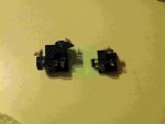
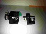
Posts:7,144 506 Shaft Pics
A few quick shots. Note shaft thickness of approx : 2.9 mm / 0.110 inch and that generous application of epoxy does not slow things down.
Steve Attached Thumbnails
Kyrie Eleison!
*****************
Thanks Steve. This picture shows a few things perhaps not intended. For one thing, it shows how the scanners can be rotated all the way around without breaking. (There is no "shaft stop".) Our actuators and scanners have two possible resting positions, located at 180-degree angle. One really cool thing to see is -- if you apply power to the scanners now, the mirrors will instantly flip into the proper orientation. Normally they will stay there too. In Steve's case, I guess he rotated them...
For another thing, Steve's pictures clearly show how we support the back of the mirror with the shaft.
And finally, one thing we haven't talked too much about is the "Darth Vader Shaped" X mirror. This allows us to have exactly the same inertia as the Y mirror, without increasing mirror width or length (either dimensional increase being bad for cross-axis wobble).
By the way, we're going to reduce the front dimension of the X-Y mount by around 0.1 inches, so the final package will be a bit smaller than what you're seeing here. Reply Reply With Quote .
--------------------------------------------------------------------------------
Today, 13:08 #216 swamidog
Senior Member Join Date:Nov 2006
Location:Goodyear, AZ
Posts:1,542,920
the bolt through mounting hole is a pleasant surprise.
just when i was getting good at making blind holes and countersinking in my baseplate. tell me it's sized for 1/4-40.
Originally Posted by mixedgas
A few quick shots. Note shaft thickness of approx : 2.9 mm / 0.110 inch and that generous application of epoxy does not slow things down.
Steve
((((((((((((((((((
Originally Posted by johnjack
I keep hearing talking about these new scanners and how they are better than other 30K scanners because they can deliver that speed at larger angles. So what is the angle for the 30K pattern?
Great question. Perhaps you missed it, but check out this video, because your question is answered within the first few minutes:
ScannerMAX Compact 506 versus DT40 - YouTube
On these particular amps, we were able to get 14.5 degrees with the ILDA test pattern at 30K. That's impressive, and more than I've seen from Cambridge 6800s or 6210s driven with amps that don't use an H-bridge.
But I honestly hate the question of "angle with the ILDA test pattern" because, unless you've been around for a while, and read a number of posts, this might incline people to think that 14.5 degrees is the maximum angle for all patterns. This "angle with the ILDA test pattern" only governs a single feature of the ILDA test pattern. Most other features will continue to look good even if the angle is increased. I think this will be visible on the video I made for Norty here:
DT40 amps running Compact 506 with 5mm square beam mirrors - YouTube
As can be seen in previous posts by Norty, these scanners can scan a lot wider than just 14.5 degrees. Norty is getting angles of 50 degrees and in the first video I mentioned above, the angle we were seeing is around 53 degrees or so.
For reference, if you accomplish an angle of 53 degrees, you will have a "one for one" projection situation. What I mean is, if you are 10 meters from the screen, then you'll be able to produce images that are 10 meters high and 10 meters wide.
Bill Reply Reply With Quote .
--------------------------------------------------------------------------------
Today, 13:12 #218 Pangolin
Senior Member
Join Date:Apr 2006
Location:Orlando, FL - USA
Posts:1,367
Originally Posted by swamidog
the bolt through mounting hole is a pleasant surprise.
just when i was getting good at making blind holes and countersinking in my baseplate. tell me it's sized for 1/4-40.
Well there are a lot of mounting options including "from the top" and "from the bottom". (I just noticed on this mount we don't have any holes "from the front" but that is also typical for us...)
And yes, you can fit a #4-40 screw through those counter-bore holes, or I think M3 or maybe larger metric...
Bill Reply Reply With Quote .
--------------------------------------------------------------------------------
Today, 13:13 #219 mixedgas
Infinitus Excellentia Ion Laser Dominatus Join Date:May 2007
Location:A lab with some dripping water on the floor.
Posts:7,144
Mounting holes, two of them. One under the scanners, one through the block long ways from the vertical. Appear to be clearance holes for M3, which is fine with me. My company uses M3 for nearly everything, so I'm used to it. Its a nice thread pitch and easy to tap for. I've never had much trouble finding M3 at a hardware store, nation wide(USA). 4-40 would fit as well.
Both holes are top accessible. No blind holes, no need for bottom access. I tapped the one hole for 8-32 so it sits on a standard optical post. I was able to do that and retain the 4-40/M3 functionality. I would not do that for anyone else's mount, for heat sinking reasons. The 1/2" diameter post, two inches long to a large baseplate, was enough heat sink at normal room ambient. These run cool.
You can also unbolt the side and flip the entry by design. You have to interchange Motor+ and Motor- on the cable, on one galvo. That's it, no other magic required. So no need for finding a different left or right hand block if your design requires it.
Having no stops is a serious advantage, for shipping and handling. If the mirror is rotated, the amp surges a bit, and flips the mirror, and the galvo starts scanning. Which is a function of the position sensor design. If you over drive it, you can go a long way without fear of damage. This is great for setup, if your software does not retain the angle settings.
Also the mirrors are far enough away from each other that you cannot "crash" the mirrors into each other. This alone is worth the price of admission.
I rotated the mirrors to get good shaft views. The scratch on the top of the mounting block is mine, from clamping for a quick test.
I flipped the cables during testing to interchange the axis connections. The "Darth" Mirror's inertia closely matches the paddle mirror, so there was no harm done and the tuning was close enough, nothing oscillated.
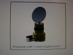
These are the smaller mirror set, great for tight beams.
Steve Last edited by mixedgas; Today at 13:40. Kyrie Eleison!
888
norty303
Senior Member Join Date:Feb 2008
Location:East Sus***, England
Posts:3,513
I think Imeasured the through holes at 3.3mm, which meant they were ideal for tapping for M4*0.7, which I did and screwed in from underneath.
There are also a series of smaller blind threaded holes on mine, but not quite M3 - so must be an imperial size.
I chose to screw from underneath, partly because getting a hex bolt through the centre hole from the top would mean removing both galvos from the block.
If this hole was moved forward (toward the 'front' of the block) and to the corner, it would be possible to access it from above with both galvos in place, and put it more diagonally opposite the other hole.
However, I 'think' it might be placed thusly, because you can fix the centre, and rotate the block for final alignment, and the beam should still be centred on the mirror.
P.S. without wishing to derail this thread further, but related to the glut of threads and discussion about 'speed' and 'kpps' currently, do we need to revisit 'why' we use the ILDA pattern at 8 degrees and 30k as a 'standard'?
I thought it would be obvious that it is simply a common benchmark by which to judge performance, which tests a number of different parameters/properties, but it would seem that some people think that it defines max angle for graphics, or isn't then applicable when not scanning beams at larger angles, and other such strangeness.
I liken it to some of the computer graphic chip benchmark programs - it taxes a scanner set in a particular way, that is consistent and repeatable across any scanner platform.
I seem to recall there was a similar derailment discussion on the ill fated EMS thread of recent history. Last edited by norty303; Today at 13:45.
)))))))))))))))))
Edited-- sry Must have double copied-
The 'Saturns' mentioned will the the higher cost Pangolin scanners. More expensive and even more advamnce/fasster (I assume) and likely even bigger scan angles---
hk
Pangolin, famous for their software has come out with some scanners of their own design- said to perform like Cambridge Tech with a price closer to DTs-
The ones we can afford are mode "SCANNERMAX 506'- and they are 30k- but not at all like any 30K most of us have seen-- I will try place the posts from there in an easy way for reading and posting your comments= but remember these posts are not put here by the authors--so if you have a question for one of those whose work i have copied you need to ask them- and to do that in most cases you will need to go 'over there'..
Much of this comes to us from Bill Benner- he has given me the Ok to start this thread. There is already some scanner info in this section and also at the link in my sig-- thanks to Dan 'Things'
hak
&&&&&&&&&&&&&&&&&&&&&&
Okay-- first I apologize if the order of these 'quotes' is not perfect-
What I had been doing is copypasta interesting posts and replies to them into note- and had to reboot so i just pasted all those into word- I will copy some here in the OP and will let you have some time to read then wil post more- much of this comes from [angolin Bill Benner and involves a new scanner set Pangolin is offering-(the''506' 30k) There is quite a stir about these and two beta testers('Mixed Gas' Steve Roberts and Norty from the UK) & they have a huge review thread going on over 'there' - So to a see a more complete posts in order you are free to lurk on over there- they are open 24/7 .. as usual there the topic strays off with stuff about lenses etc but in some way all is good stuff to know. -- Norty, Bill and Steve have given me the OK to post their stuff .
here-
I know right away some will ask me the prices- so far they have not been given out- I DO know they hope to be priced along the lines of the best from China- and so far that =means its going to be pretty much Dragon Tiger 40K vs Pangolin 506 50K--
Its a long but good read and I feel lucky to have all this given out to read and learn from- scanners are pretty complex and not simple for me to fully understand. --
***************************************************+
long LONG POSTS ON scannermax 506 (Pangolin)
AND SCANNER INFO= FROM PLex
____________________
OO
SCANNERMAX 506
VID
From Bill---in re lenses to make audience scanning safe
**********************************
Hi Keith,
As I said, we actually have a few lenses that do what you need, and do it really well. One of them is being reviewed by AVI right now on a real dome. If we like what we see, then that lens will be a relatively inexpensive option, and one we can deliver within a few weeks. If we think that the divergence increase is too much, then we have an alternative design that we know is super-duper fantastic, but it will take a bit longer to bring to market, because we'll have to develop a lens barrel for it. That means design, machining, etc.
Regarding the scanners themselves, we did our own comparison between Compact 506 and DT40, since that was a topic of discussion on another thread. You can see our video here:
ScannerMAX Compact 506 versus DT40 - YouTube
Bill
_________
Bill,
Thanks a lot for the video. There is so much useful information provided with a video demonstration. For example, the layout of your mounting block is now obvious. Something I have noticed in aligning projectors is the inevitable deterioration of a hard won RGB far field spot to a wider far field line. The scanned line width is never as good as the static beam even when the beam path includes the scanner mirrors ( off, non-scanning). I have always attributed this to a combination of tracking errors and mirror surface distortion under G loading. In both the test patterns and the show the 506 seems to produce sharper lines that are sometimes more obvious and sometimes less. To be fair, do you agree? And if you do, can the effect of the laser sources be isolated to demonstrate this more effectively or predictably?
Larger laser sources (larger beams require larger scanner mirrors) will more likely be used at larger distances and the need for lower divergence will be greater. EMS and Nutfield both changed to fused silica (from what I do not know) to enhance their mirror stiffness ostensibly to allow a thinning (lightening) of their mirrors. What is not discussed is the quantitative effect of mirror stiffness (ie silicon) on the mirror itself. Certainly, if high enough scanning speeds can break a mirror then something short of that has to be undermining a high quality, low divergence laser beam.
*******************
01-21-2014, 17:20 #201 Galvonaut
Senior Member Join Date:Aug 2013
Location:West Sus***
Posts:868
Originally Posted by White-Light
Didn't know you were after a graphics solution Keith.
No worries. Also after beams but don't really require massive angles for them. Some 506s wouldn't go amiss though. Reply Reply With Quote .
--------------------------------------------------------------------------------
01-21-2014, 21:01 #202 Pangolin (Bill)
Senior Member
Join Date:Apr 2006
Location:Orlando, FL - USA
Posts:1,367
Hi Keith,
As I said, we actually have a few lenses that do what you need, and do it really well. One of them is being reviewed by AVI right now on a real dome. If we like what we see, then that lens will be a relatively inexpensive option, and one we can deliver within a few weeks. If we think that the divergence increase is too much, then we have an alternative design that we know is super-duper fantastic, but it will take a bit longer to bring to market, because we'll have to develop a lens barrel for it. That means design, machining, etc.
Regarding the scanners themselves, we did our own comparison between Compact 506 and DT40, since that was a topic of discussion on another thread. You can see our video here:
ScannerMAX Compact 506 versus DT40 - YouTube
Bill Reply Reply With Quote .
--------------------------------------------------------------------------------
01-21-2014, 23:03 #203 Bradfo69
Senior Member Join Date:Jul 2010
Location:Wilmington, DE
Posts:2,757
Nice video Bill. Thank you! Reply Reply With Quote .
--------------------------------------------------------------------------------
Yesterday, 05:56 #204 Galvonaut
Senior Member Join Date:Aug 2013
Location:West Sus***
Posts:868
Originally Posted by Pangolin
Hi Keith,
As I said, we actually have a few lenses that do what you need, and do it really well. One of them is being reviewed by AVI right now on a real dome. If we like what we see, then that lens will be a relatively inexpensive option, and one we can deliver within a few weeks. If we think that the divergence increase is too much, then we have an alternative design that we know is super-duper fantastic, but it will take a bit longer to bring to market, because we'll have to develop a lens barrel for it. That means design, machining, etc.
Regarding the scanners themselves, we did our own comparison between Compact 506 and DT40, since that was a topic of discussion on another thread. You can see our video here:
ScannerMAX Compact 506 versus DT40 - YouTube
Bill
I look forward to hearing more news
Just watched the video on the other thread - Nice results!
Keith Reply Reply With Quote .
--------------------------------------------------------------------------------
Yesterday, 10:51 #205 planters
Senior Member Join Date:Feb 2011
Location:New Hampshire
Posts:1,767
Bill,
Thanks a lot for the video. There is so much useful information provided with a video demonstration. For example, the layout of your mounting block is now obvious. Something I have noticed in aligning projectors is the inevitable deterioration of a hard won RGB far field spot to a wider far field line. The scanned line width is never as good as the static beam even when the beam path includes the scanner mirrors ( off, non-scanning). I have always attributed this to a combination of tracking errors and mirror surface distortion under G loading. In both the test patterns and the show the 506 seems to produce sharper lines that are sometimes more obvious and sometimes less. To be fair, do you agree? And if you do, can the effect of the laser sources be isolated to demonstrate this more effectively or predictably?
Larger laser sources (larger beams require larger scanner mirrors) will more likely be used at larger distances and the need for lower divergence will be greater. EMS and Nutfield both changed to fused silica (from what I do not know) to enhance their mirror stiffness ostensibly to allow a thinning (lightening) of their mirrors. What is not discussed is the quantitative effect of mirror stiffness (ie silicon) on the mirror itself. Certainly, if high enough scanning speeds can break a mirror then something short of that has to be undermining a high quality, low divergence laser beam. Reply Reply With Quote .
--------------------------------------------------------------------------------
Yesterday, 11:24 #206 mixedgas
Infinitus Excellentia Ion Laser Dominatus Join Date:May 2007.
Posts:7,144
Location:A lab with some dripping water on the floor
Mirror photo this afternoon before I ship the system back. You WILL be impressed.
Steve Kyrie Eleison! Reply Reply With Quote .
--------------------------------------------------------------------------------
Yesterday, 12:41 #207 Pangolin
Senior Member
Join Date:Apr 2006
Location:Orlando, FL - USA
Posts:1,367
Originally Posted by planters
In both the test patterns and the show the 506 seems to produce sharper lines that are sometimes more obvious and sometimes less. To be fair, do you agree?
Hehe, I will always agree that our stuff looks better than anyone else's. This may seem boastful or arrogant but it's not meant to be. Everything about our scanners is DESIGNED. There isn't a single part that is used unmodified and off the shelf. Even the bearings are made special just for us and just this morning, I got off the phone with a lubricant manufacturer who will be custom-blending lubricants just for us.
But to speak precisely to your topic, what you're talking about is called "dynamic stiffness" and yes, this plays a dramatic role in what opticians call the "resolution" of the image. If the beam becomes spread out just as a result of your scanning action, then "resolution" has become decreased. When designing resonant scanners (which typically have far higher torques) the designer actually STARTS with the mirror, to ensure dynamic stiffness is there, and then works outward on the mechanics to hold such a sufficiently-stiff mirror in the first place.
The work we have done in the field of rotor dynamics (mentioned and shown on my video) speaks to essentially the same thing, but in two dimensions.
Originally Posted by planters
EMS and Nutfield both changed to fused silica (from what I do not know) to enhance their mirror stiffness ostensibly to allow a thinning (lightening) of their mirrors.
I don't know of anyone else who has done the degree of study we have on the effect of mirror thickness on overall rotor dynamics. Remember, the mirror is not "in a vacuum". The mirror is mounted to a rotor. One thing we show is that it doesn't matter how thick (or almost how thin) the mirror is on a scanner with a long rotor (or small-diameter shaft), resonances will happen at a similar frequency. The mirror may dominate rotor dynamics (and dynamic stiffness) in certain scanners, but not others.
And -- again, it may sound boastful or arrogant -- but I haven't seen either of the two companies you mentioned above do any real engineering. I haven't been inspired or impressed by even so much as a single thing that these other companies have done. And finally, I believe that the work we do can't even be compared to the work that these other guys do. If you (the reader) thinks this sounds arrogant, I understand and even agree, it sounds arrogant. But if you visit both companies (as Steve has), look at our parts under a microscope, and see the degree of real engineering that goes into these products, then you'll understand what I'm talking about.
Regarding Fused Silica, that's the material we have always used when we use optical glass. But Fused Silica as compared to what? BK7? As far as I know, at least in the distant past EMS used mirrors made from something called Sodalime glass, made by Knight Optical in UK (because that's their standard material). It's not as stiff, and it's also heavier (but much less expensive than Fused Silica).
But when you "do the math" on all of these materials, the real difference in the actual application between Fused Silica (which is the most expensive and thus rarest used), BK7 and Sodalime Glass, the actual and tangible difference is negligible. We use the most expensive, best, and stiffest because we always want the absolute best performance possible. The topic of cost rarely comes up when we are discussing parts with vendors.
Originally Posted by planters
What is not discussed is the quantitative effect of mirror stiffness (ie silicon) on the mirror itself.
This was discussed, or at least alluded in my video. Silicon is anywhere between twice and four times as stiff as Fused Silica (depending on the angle of stress) while being negligibly heavier. So silicon is a clear winner as a mirror substrate. But silicon is harder to process and more expensive. Even setting cost aside, you need to actually find companies who can do the job well and consistently. Because of this, I've only seen us and Cambridge using it up until now.
Bill Last edited by Pangolin; Yesterday at 12:47
(((((((((((((((((((((
planters
Senior Member Join Date:Feb 2011
Location:New Hampshire
Posts:1,767
Bill,
Not to sound arrogant, but as you know, I know all this. Yet, to paraphrase... "it does NOT go without saying", it IS useful to specify these interactions. However, what I was alluding to is that like the video where the effect of twisting and bending and tracking errors must be present, would it be possible to demonstrate this? I'm not sure to what extent the line widths for the different patterns and scanners were effected by camera focus and zoom (there was a fair amount of this) and laser focus.
Without thinking this through too thoroughly, what about the sharp corner of a pattern (for X and Y) with a single color diode to avoid DPSS modulation delays? Mount the camera on a tripod and ramp up the speed to reveal dynamic effects. Repeat for the other scanner. What do you think?
*****************
Hi Planters,
Yes, it's clear from your own past videos that you know your stuff too! On lines being scanned, what you're talking about could only be caused by:
1) flatness of the mirrors themselves
2) dynamic stiffness of the mirror -- mirrors that are so thin, that torsional forces on the mirror actually cause them to twist while scanning, thus spreading out the beam.
3) a general lack of stiffness in the entire system
Regarding my point number 1, we pay a lot for mirrors, and I suspect others pay much less. This is an area where you get what you pay for...
Regarding my point number 2, the fact that our shafts are 50% larger than everyone outside the USA (and 25% larger than those inside the USA) coupled with the fact that we actually support the back of the mirror helps dramatically in this area.
Regarding my point number 3, this is something even we had to learn. When creating the Saturn 1, we actually created a scanner whose entire system inertia was only 0.008 GM*CM2. When we projected images with it, what we noticed was that the corners actually looked fatter. When we used a tiny and tightly-focused laser, we found that the beam actually wasn't coming to a stop on the corner but rather was drawing a tiny circle and squiggling around. Once we discovered this, we re-visited scanners made by other companies and surprisingly (or perhaps not surprisingly) we saw exactly the same thing, especially scanners made by the two manufacturers you mentioned above. It was this discovery which stopped us in our tracks, and encouraged us to hire a guy from Boeing who does rotor-dynamic analysis as a living, and help us to fully understand this. It is a result of his work that we re-endineered all of our products. Now you won't find squiggles or wiggles in any of our products, and things come to a complete stop on the corners.
In many cases, a fat laser beam can mask what's happening on the corner, and hide problems. When I am doing work on our scanners, I actually use a focused, single-color laser beam for this purpose. In the side-by-side video, it was impossible because already the point was to compare two full-color projectors (each laser having a different divergence and beam diameter). We were trying, as much as possible, to have as good of a side by side comparison as we could.
By the way, "tracking error" is a term used in servo design. It only means the amount of TIME between the command signal and position signal. I doubt that "tracking error" (at least in servo terminology) has anything to do with what you're seeing. After all, "tracking error" is actually always present even when scanning very slowly, and should be substantially similar in all 30K scanners, regardless of who they're made by.
Originally Posted by planters
Without thinking this through too thoroughly <snip> What do you think?
Hehe. What I think is that we've already done a thorough analysis of this. For everyone else, it's possible for people to Google "resonant frequency of cantilever beam" and similar topics and see for themselves on sources like Wikipedia that when you make a mirror 1mm thick, it has far better characteristics than when you make a mirror 0.7mm thick. When you increase the diameter of a shaft by 50% it actually makes the shaft more 5 times stiffer! All of these things should be understandable after doing a bit of reading on the internet...
And lastly, I think no matter what we do, some people will always have questions. Already on another thread here on PL, we have a guy doubting that the tests were performed correctly and consistently, or questioning the role that camera angle or shutter settings played in the test. I think no matter what we do, there will always be doubters and such. So we only present the physics behind what we're doing, and let people come to their own conclusions...
Bill Last edited by Pangolin; Yesterday at 15:16.
*********************
@Kecked, we had the Boeing guy do an analysis of 6215 with 3mm mirrors and he found that you'll get into wobble at around 45K. This confirmed what we are also seeing in real life. If you TUNE and operate the scanners to 30K, you will not notice this. But then the only benefit to having 6215 will be the angle at which you can project.
@Planters, I'll be acquiring EMS 8000s soon and will be able to fully understand the implications myself. (As you've learned about me, I never believe the hype...) Tom is indeed always improving. This much is impressive. He's never a stopped target. The only problem I have is the choices he makes at each stop are not very impressive (to me)... I'm sure once I announce my findings (which I typically do in private directly to him) he will work on them some more, and come up with EMS9000...
Bill Reply Reply With Quote .
--------------------------------------------------------------------------------
Today, 12:42 #213 johnjack
Junior Member Join Date:Jan 2014
Posts:10
I keep hearing talking about these new scanners and how they are better than other 30K scanners because they can deliver that speed at larger angles. So what is the angle for the 30K pattern? Reply Reply With Quote .
--------------------------------------------------------------------------------
Today, 12:58 #214 mixedgas
Infinitus Excellentia Ion Laser Dominatus Join Date:May 2007
Location:A lab with some dripping water on the floor.
Posts:7,144 506 Shaft Pics
A few quick shots. Note shaft thickness of approx : 2.9 mm / 0.110 inch and that generous application of epoxy does not slow things down.
Steve Attached Thumbnails
Kyrie Eleison!
*****************
Thanks Steve. This picture shows a few things perhaps not intended. For one thing, it shows how the scanners can be rotated all the way around without breaking. (There is no "shaft stop".) Our actuators and scanners have two possible resting positions, located at 180-degree angle. One really cool thing to see is -- if you apply power to the scanners now, the mirrors will instantly flip into the proper orientation. Normally they will stay there too. In Steve's case, I guess he rotated them...
For another thing, Steve's pictures clearly show how we support the back of the mirror with the shaft.
And finally, one thing we haven't talked too much about is the "Darth Vader Shaped" X mirror. This allows us to have exactly the same inertia as the Y mirror, without increasing mirror width or length (either dimensional increase being bad for cross-axis wobble).
By the way, we're going to reduce the front dimension of the X-Y mount by around 0.1 inches, so the final package will be a bit smaller than what you're seeing here. Reply Reply With Quote .
--------------------------------------------------------------------------------
Today, 13:08 #216 swamidog
Senior Member Join Date:Nov 2006
Location:Goodyear, AZ
Posts:1,542,920
the bolt through mounting hole is a pleasant surprise.
just when i was getting good at making blind holes and countersinking in my baseplate. tell me it's sized for 1/4-40.
Originally Posted by mixedgas
A few quick shots. Note shaft thickness of approx : 2.9 mm / 0.110 inch and that generous application of epoxy does not slow things down.
Steve
((((((((((((((((((
Originally Posted by johnjack
I keep hearing talking about these new scanners and how they are better than other 30K scanners because they can deliver that speed at larger angles. So what is the angle for the 30K pattern?
Great question. Perhaps you missed it, but check out this video, because your question is answered within the first few minutes:
ScannerMAX Compact 506 versus DT40 - YouTube
On these particular amps, we were able to get 14.5 degrees with the ILDA test pattern at 30K. That's impressive, and more than I've seen from Cambridge 6800s or 6210s driven with amps that don't use an H-bridge.
But I honestly hate the question of "angle with the ILDA test pattern" because, unless you've been around for a while, and read a number of posts, this might incline people to think that 14.5 degrees is the maximum angle for all patterns. This "angle with the ILDA test pattern" only governs a single feature of the ILDA test pattern. Most other features will continue to look good even if the angle is increased. I think this will be visible on the video I made for Norty here:
DT40 amps running Compact 506 with 5mm square beam mirrors - YouTube
As can be seen in previous posts by Norty, these scanners can scan a lot wider than just 14.5 degrees. Norty is getting angles of 50 degrees and in the first video I mentioned above, the angle we were seeing is around 53 degrees or so.
For reference, if you accomplish an angle of 53 degrees, you will have a "one for one" projection situation. What I mean is, if you are 10 meters from the screen, then you'll be able to produce images that are 10 meters high and 10 meters wide.
Bill Reply Reply With Quote .
--------------------------------------------------------------------------------
Today, 13:12 #218 Pangolin
Senior Member
Join Date:Apr 2006
Location:Orlando, FL - USA
Posts:1,367
Originally Posted by swamidog
the bolt through mounting hole is a pleasant surprise.
just when i was getting good at making blind holes and countersinking in my baseplate. tell me it's sized for 1/4-40.
Well there are a lot of mounting options including "from the top" and "from the bottom". (I just noticed on this mount we don't have any holes "from the front" but that is also typical for us...)
And yes, you can fit a #4-40 screw through those counter-bore holes, or I think M3 or maybe larger metric...
Bill Reply Reply With Quote .
--------------------------------------------------------------------------------
Today, 13:13 #219 mixedgas
Infinitus Excellentia Ion Laser Dominatus Join Date:May 2007
Location:A lab with some dripping water on the floor.
Posts:7,144
Mounting holes, two of them. One under the scanners, one through the block long ways from the vertical. Appear to be clearance holes for M3, which is fine with me. My company uses M3 for nearly everything, so I'm used to it. Its a nice thread pitch and easy to tap for. I've never had much trouble finding M3 at a hardware store, nation wide(USA). 4-40 would fit as well.
Both holes are top accessible. No blind holes, no need for bottom access. I tapped the one hole for 8-32 so it sits on a standard optical post. I was able to do that and retain the 4-40/M3 functionality. I would not do that for anyone else's mount, for heat sinking reasons. The 1/2" diameter post, two inches long to a large baseplate, was enough heat sink at normal room ambient. These run cool.
You can also unbolt the side and flip the entry by design. You have to interchange Motor+ and Motor- on the cable, on one galvo. That's it, no other magic required. So no need for finding a different left or right hand block if your design requires it.
Having no stops is a serious advantage, for shipping and handling. If the mirror is rotated, the amp surges a bit, and flips the mirror, and the galvo starts scanning. Which is a function of the position sensor design. If you over drive it, you can go a long way without fear of damage. This is great for setup, if your software does not retain the angle settings.
Also the mirrors are far enough away from each other that you cannot "crash" the mirrors into each other. This alone is worth the price of admission.
I rotated the mirrors to get good shaft views. The scratch on the top of the mounting block is mine, from clamping for a quick test.
I flipped the cables during testing to interchange the axis connections. The "Darth" Mirror's inertia closely matches the paddle mirror, so there was no harm done and the tuning was close enough, nothing oscillated.
These are the smaller mirror set, great for tight beams.
Steve Last edited by mixedgas; Today at 13:40. Kyrie Eleison!
888
norty303
Senior Member Join Date:Feb 2008
Location:East Sus***, England
Posts:3,513
I think Imeasured the through holes at 3.3mm, which meant they were ideal for tapping for M4*0.7, which I did and screwed in from underneath.
There are also a series of smaller blind threaded holes on mine, but not quite M3 - so must be an imperial size.
I chose to screw from underneath, partly because getting a hex bolt through the centre hole from the top would mean removing both galvos from the block.
If this hole was moved forward (toward the 'front' of the block) and to the corner, it would be possible to access it from above with both galvos in place, and put it more diagonally opposite the other hole.
However, I 'think' it might be placed thusly, because you can fix the centre, and rotate the block for final alignment, and the beam should still be centred on the mirror.
P.S. without wishing to derail this thread further, but related to the glut of threads and discussion about 'speed' and 'kpps' currently, do we need to revisit 'why' we use the ILDA pattern at 8 degrees and 30k as a 'standard'?
I thought it would be obvious that it is simply a common benchmark by which to judge performance, which tests a number of different parameters/properties, but it would seem that some people think that it defines max angle for graphics, or isn't then applicable when not scanning beams at larger angles, and other such strangeness.
I liken it to some of the computer graphic chip benchmark programs - it taxes a scanner set in a particular way, that is consistent and repeatable across any scanner platform.
I seem to recall there was a similar derailment discussion on the ill fated EMS thread of recent history. Last edited by norty303; Today at 13:45.
)))))))))))))))))
Edited-- sry Must have double copied-
The 'Saturns' mentioned will the the higher cost Pangolin scanners. More expensive and even more advamnce/fasster (I assume) and likely even bigger scan angles---
hk
Last edited: