DJZ
0
- Joined
- Aug 27, 2008
- Messages
- 270
- Points
- 0
daguin said:I'm about 60-70% done with mine. I am using 25 Ohm pots and just discovered that they will NOT stop the motors (12V). I'm going to have to put in a couple of switches tomorrow. Then about the only things left will be the laser/heat sink and the fan. Oh yeah, I've yet to figure out how I'm going to get the power into the box.
Peace,
dave
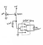
Dave, how are you guys attaching the pot to these motors? Are you just wiring the wiper of the pot to the motor or do you go through a transistor? An ideal method would be to attach the wiper of a 1 or 10K pot to the base of a darlington transistor. Then run the motor off the emitter of the transistor. You can also run the emitter through a relay so you can reverse the direction of the motor. It would also help to add something around a 1uF cap to the emitter of the transistor to common as well. This should give a very smooth/linear control throughout the run of the pot.
I really like the photo above of the 405nm abstract, very pretty stuff!


")