Welcome to Laser Pointer Forums - discuss green laser pointers, blue laser pointers, and all types of lasers

LPF Donation via Stripe | LPF Donation - Other Methods

Links below open in new window

ArcticMyst Security by Avery

Homemade Scanning Laser Color Projector/TV

Joined
Apr 28, 2009
Messages
63
Points
8
You just adjust the max value of the current to be the Imax of the laser diode.

If the video signal becomes too high somewhere while experimenting, power supply will fail to supply current greater than Imax. It is that simple.

After finding the critical values of all parameters you may replace yor source with a constant Vcc.

Sorry, English is not my mother language. Maybe I cannot express myself correctly.

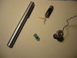
Edit: The current limitting power supply in that picture is not a DDL. It can deliver any current below the limitting value to the circuit

picture is on page5 post 124
 
Last edited:


LSRFAQ

0
Joined
May 8, 2009
Messages
1,155
Points
83
Reply to kingbower and dasraiser


Contrary to the common belief, DPSS green lasers are susceptible to high speed analog modulation.

Not quite right at all.

Only at very low powers, on the order of a few mW. Only in lasers where the pump diode is so small, it sees a infinite heat sink.

Steve
 

LSRFAQ

0
Joined
May 8, 2009
Messages
1,155
Points
83
quote

Contrary to the common belief, DPSS green lasers are susceptible to high speed analog modulation.

end quote.

Not quite right at all.

Only at very low powers, on the order of a few tens of mW. Only in small DPSS lasers where the pump diode is so small, it sees a infinite heat sink and thus does not shift in wavelength much, and where thermal distortion in the ND:Yag is low. Because he is showing video, he has a moderately constant average power and the laser is somewhat thermally stable. If he had to wrench the diode from blanked to full on at high powers, he would see the same modulation problems the rest of us have.

In other words, it does not scale to large scale displays beyond a few tens of milliwatts.


As for the power supply,

What he is trying to say is he has a constant current driver with good compliance and then mounts a series modulating transistor in the cathode of the diode. He is then lucky that he is operating in the moderate current, some what linear regions with his diodes. You then have to very carefully adjust the base current of the transistor to get it in its linear region. Fine for a one off in the lab, but hell to manufacture commercially.

No emitter degeneration, no feedback, no Miller effect compensation, and if you looked at the diode current on a scope, its ringing like mad. If you try this, keep the cables VERY short and the currents to the diode low. If you want to do it better, place the transistor in shunt across the laser diode, with a small series RC for degeneration in the emitter lead, and invert the video. This way the constant current source does not see wild fluctuations and is less likely to spike, ring, or oscillate.


Steve
 
Last edited:
Joined
Feb 15, 2010
Messages
31
Points
0
These are the problems I was talking about ;-)

The modulation of green lasers is far from simple. What is the maximum output of the green laser you used for the previous screen shots?
 
Joined
Apr 28, 2009
Messages
63
Points
8
Reply to dasraiser:

I forgot to say, if there is any built in elecronics in your green laser, such as DDL, you should take it out.

There is a picture of the lasers below, used in this scanner :

For some pictures and more info:
http://laserpointerforums.com/members/sltvm2007/albums/homemade-laser-scanner/

http://laserpointerforums.com/f47/homemade-scanning-laser-color-projector-tv-32628.html

Kuntman's Color Projector/ TV:
YouTube - Laser TV - Projector (no-MEMS, no AOM)

3D Visual Effect by Kuntman's Scanner:
YouTube - 3D Visual Effect (Kuntman's Scanner, Laser Projector/TV)

Videos:
YouTube - homemade laser projector tv (no-MEMS, no-AOM)

YouTube - laser tv (without MEMS)
 

Attachments

  • green lasers.JPG
    green lasers.JPG
    78.4 KB · Views: 854
Last edited:
Joined
Feb 15, 2010
Messages
31
Points
0
What is the maximum power you feed the green laser? When you plan to add the blue (or violet) channel? In these days the 445 nm blue ones from Casio projector are quite simple to find, and a 405 nm one I think would do it too.
 
Joined
Apr 28, 2009
Messages
63
Points
8
Video amp of that green laser circuit was designed and made by one of my students when I was working for the university. Nevertheless, I have a look at the board. There used NE592 as a video amp and it drives a transistor (BC 140) with a small heatsink. You may estimate the input power from the datasheet of these components.

But before experimenting, you need a high speed XY scanner synchronized to the video. Otherwise you have no means to see what is going on.

The common belief ''green lasers cannot be modulated'' comes mainly from the lack of such an instrument. You cannot find the critical values of the parameters shown in that diagram, unless you are monitoring the image scanned by a suitable projector. Because that parameters all depend on the characteristics of a particular laser.

At the beginning you may see no sign of modulation. But when you come closer to the critical values a blurred image will appear. And the rest will follow immediately.
 
Joined
Feb 15, 2010
Messages
31
Points
0
So you are saying that if you use a fast mpdulation you won't have the problems of the "slow" modulation? It's interesting.
 
Joined
Apr 28, 2009
Messages
63
Points
8
Reply to kingbowser and LASERFAQ,

That may be right: What is imposible in slow modulation somehow turns out to be possible in fast modulation. Perhaps the answer is hidden in the physics of the crystal. As noted by LASERFAQ :
''...where thermal distortion in the ND:Yag is low. Because he is showing video, he has a moderately constant average power and the laser is somewhat thermally stable.''

Let me try to make this point clear:
In order to see what happens, consider a square wave modulation: At low frequencies, average power calculated in successive time intervals ''t'' (1 ms for instance) will not be equal (constant), if ''t'' is smaller than the period ''T'' of the square wave. ( ''t'' is assumed to be long enough that the temparature of the crystal undergoes great fluctuations during that period.)

But if we increase the frequency of the square wave so that ''T'' becomes very small than ''t'', average power calculated in succesive time intervals of ''t'' become almost equal.

In our case ''T'' is in the order of 0.1microseconds. And hence, the crystal can be considered thermally stable, provided that video content does not undergo drastic changes.

It is clear that, same explanation does apply to the modulation of green lasers of any power. Therefore fast modulation of green lasers is no way limitted to 0.1 mW range. Avatar of the present thread is an evidence of this. That picture was taken from an image of dimensions 20x30 cm performed on a screen 35 cm away from the scanner by a 50 mW green laser . And in the video in youtube you may see that the image is still visible under 200 watt spot lights!
 
Last edited:
Joined
Oct 26, 2007
Messages
5,438
Points
83
Sorry if this has been explained, but your diagrams show the mirror strip for the fast axis, but what are you using for the slow axis?
 
Joined
Apr 28, 2009
Messages
63
Points
8
Slow axis is not critical, any galvo can be used for the slow axis.
The simplest one is a high torque galvo, driven sinusoidally with a suitable time delay and flyback blanking.

For some pictures and more info:
http://laserpointerforums.com/members/sltvm2007/albums/homemade-laser-scanner/

http://laserpointerforums.com/f47/homemade-scanning-laser-color-projector-tv-32628.html

Kuntman's Color Projector/ TV:
YouTube - Laser TV - Projector (no-MEMS, no AOM)

3D Visual Effect by Kuntman's Scanner:
YouTube - 3D Visual Effect (Kuntman's Scanner, Laser Projector/TV)

Videos:
YouTube - homemade laser projector tv (no-MEMS, no-AOM)

YouTube - laser tv (without MEMS)
 
Last edited:
Joined
Apr 28, 2009
Messages
63
Points
8
New scanner finished.
 

Attachments

  • Kuntman's scanner2.JPG
    Kuntman's scanner2.JPG
    89.9 KB · Views: 2,178
  • Kuntman's scanner3.JPG
    Kuntman's scanner3.JPG
    93.5 KB · Views: 5,665
  • Kuntman's scanner1.JPG
    Kuntman's scanner1.JPG
    89.6 KB · Views: 5,013
Joined
Apr 28, 2009
Messages
63
Points
8
Block Diagram for the Electronic Circuit

Electonic circuit consists of the following parts:

Synch. separator
Divide by 2 circuits
Delay lines
RGB separator
Video amplifiers
Flyback blanking
Laser drivers
Filters
Vertical mirror driver
Horizontal mirror driver
 

Attachments

  • Block Diagram.JPG
    Block Diagram.JPG
    98 KB · Views: 9,895
Last edited:


Top