Welcome to Laser Pointer Forums - discuss green laser pointers, blue laser pointers, and all types of lasers

LPF Donation via Stripe | LPF Donation - Other Methods

Links below open in new window

ArcticMyst Security by Avery

Help with audio amp D:

Joined
Oct 26, 2007
Messages
5,438
Points
83
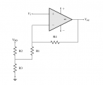
But that's not reflected in the diagram. Also if you don't buffer it with an amp for your virtual ground, the resistors can affect the ground.


NME

0
Joined
Mar 21, 2011
Messages
6
Points
0
Ya na he's got the right idea with the voltage divider. You're making the mistake of using your V- as ground with your opamp resistors and LEDs. Go back to your schematic in post#16: The two series resistors running parallel to your voltage source; in the middle of those is your virtual ground.
You could use Bionic-Badgers virtual ground circuit, but I wouldnt think it necessary introducing another opamp and extra components unless problems persisted. The smaller those voltage divder resistors values, the more stable your virtual ground reference will be, it will however burn alot more power.
 
Joined
Oct 26, 2007
Messages
5,438
Points
83
The reason why I suggest a buffered virtual ground is that if you don't, the voltage divider you're using for "virtual ground" will be affected by (and in turn also affect) the feedback loop. For example:

attachment.php


The op amp is in negative feedback mode, so V1 is also at the junction between R1 and R4. The current relationship at the R1,R2,R3 junction is therefore:

Code:
V3 / R3 =  [(Vdd - V3) / R2] + [(V1 - V3) / R1]

V3 = [R1*R3*Vdd + R2*R3*V1] / [R1*(R2+R3)+R2*R3]

Too complicated ; didn't read ...

In other words, the value of V1 will affect the value of V3 -- the virtual ground reference the op-amp depends on.

Worse is when the virtual ground is shared with multiple op amps, like in Sourcegeek's diagram, which means one op amp can affect the other.

It's always best to use a buffered virtual ground so that you can "lock" that voltage at a specific value.
 

Attachments

  • opamp_virtual_ground.png
    opamp_virtual_ground.png
    10.3 KB · Views: 1,858
Last edited:

NME

0
Joined
Mar 21, 2011
Messages
6
Points
0
You are right of course, and indeed for Sourcegeeks resistor values this will have a large effect. However, if he were to choose his resistor values carefully he could minimise this to a large extent without employing your ideal, yet component requiring, fixed voltage reference.
If the resistor values of R1 and R4 are much larger than R2 and R3, V1 would have a very small effect on V3 and visa versa. If you rearrange the second formula above you get:
Code:
V3 =  [V1*R2*R3]/[R1*R2 +R3*(R1+R2)]    +    [Vdd*R1*R3]/[R1*R2 +R3*(R1+R2)]
If you look at the top line of the second term/fraction you'll see it contains R1, where the top line of the first term contains only R2 and R3. Also note Vdd will always be much larger than V1. Hence, if R1 is much bigger than R2 and R3, the second term will largely dominate, comprising most of the value of V3.
Thats what i meant by saying that decreasing values of R2 and R3 would increase the stability of the virtual ground, or indeed; increasing the values of R1 and R4 proportionally.
Considering the resitor values in a typical feedback opamp circuit should be in the realm of at least 10's of kilo-ohms anyway, this is a viable alternative.


Top