Welcome to Laser Pointer Forums - discuss green laser pointers, blue laser pointers, and all types of lasers

LPF Donation via Stripe | LPF Donation - Other Methods

Links below open in new window

ArcticMyst Security by Avery

Help with audio amp D:

Joined
Oct 26, 2007
Messages
5,438
Points
83
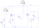
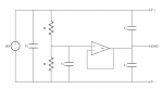
Good, you have some feedback in there. You'll want to make one of the resistors in each of the feedback resistor networks be a potentiometer so you can adjust the gain according to what your HDD galvos need. That'll require some experimentation on your part.


Joined
Feb 19, 2011
Messages
72
Points
0
When i was running all, i saw that the signal is too weak, but i have two supositions;
1- I need more volts at the input
2- I need to play with the resistors to make a higher gain

I think the second option is cheapest than the first one.. What do you think?
 
Joined
Oct 26, 2007
Messages
5,438
Points
83
Yes, I'd mess with that, but also make sure that the input power (not the input *signal*) to the amplifier you're using is sufficient too.
 
Joined
Feb 19, 2011
Messages
72
Points
0
I have now a 18V input source.. I connected it and comes again the problem:
The moving of the arm is limited and the sound is distorted.. I was finding the problem and i found that if i touch all the extremities of the OpAmp.. The moving is better...

What it means?
 
Joined
Oct 26, 2007
Messages
5,438
Points
83
Try putting some capacitors between the power (+18V) and the ground to see if that helps.
 
Joined
Feb 19, 2011
Messages
72
Points
0
Ok I think I know where.. How many capacity I need the capacitors?

Edit: I was checking with a 47uF 16V electrolitic capacitor and the moving is so awesome at low volume in the PC! I tested it with only 1 amplificator, now i will check with two.. So, thanks for all! :D

To the final i have a question... I need a heatsink or will work nice with only a fan? Thanks
 
Last edited:
Joined
Oct 26, 2007
Messages
5,438
Points
83
Good to hear it helped! You should put a somewhat bigger heatsink on the amplifier chip depending on how fast you move the galvos. For the capacitors between power and ground you can put all kinds of capacitors to try and filter out the noise.
 
Joined
Feb 19, 2011
Messages
72
Points
0
I dont know why but rarely i got today too much noise D:
What i need to do? Put more capacitors? Paralel or serial? :S

Thanks
 
Joined
Oct 26, 2007
Messages
5,438
Points
83
If you put them between power and ground you'll clean up the power noise a bit. For your signal you could try putting a very small capacitor between signal and ground to clear out the high frequency noise. It might affect your performance, but it's worth a try.
 
Joined
Feb 19, 2011
Messages
72
Points
0
Ok i solved it with capacitors..
Worked fine with only one Amp and one Hard drive, but when i connect the two (one to left, the other to right) it doens't respect if is right or left..
I mean.. If i do in the PC a left signal, both hard drives are moving! Not only the left one! And the same problem with right signal D:
What is bad? I tried too to connect some capacitors between resistor and ground, but didn't worked..

Note; Im using the center of the two resistors of the power source as reference/ground

Thanks
 
Joined
Feb 19, 2011
Messages
72
Points
0
I think I almost solved the problem, but i need something that i don't know what, see..
With this new setup; if i do a left signal, i get 100% signal on the left, but I get 5% too on the right... I think i need to filter with diodes, but I dont know

By the way, I didn't used ground in the setup because i don't know where to get it... The converter only have two cables (positive and negative) and not ground

Thanks
 

Attachments

  • circuitoactual2.png
    circuitoactual2.png
    18.5 KB · Views: 199
Joined
Oct 26, 2007
Messages
5,438
Points
83
Okay, first of all, are those resistors between your power and ground? They need to be capacitors. Resistors will just use power, but the capacitors will help clean out the noise.

Another thing: you probably ought to use a virtual ground circuit to provide the ground for your amplifiers. A virtual ground gives you a voltage reference between the two extremes of your power supply. So for example the virtual ground of your 18V source would be at 9V. It's useful so that your amplifiers can amplify signals that go negative rather than just positive. Here is a diagram you can use for your circuit:

attachment.php


The resistors in the circuit should have an equal value (100k should be a good value for both). The C1 capacitor can be virtually anything, and you can use multiple capacitors in parallel[/] as well to suppress noise. The same thing for the C2 and C3 capacitors. Just pick some capacitors that reduce the noise. The amp in the middle just has a wire from the output to the inverting input so that it acts like a buffer, it is powered from the V+ and V-. On the right-side of the circuit, hook the V+ to the +Vs (the positive POWER input) of your TDA2030 amplifiers, and the V- to the -Vs (the negative POWER input) of your TDA2030 amplifiers.

For the GND, connect that to all your ground sources, which means the ground for your signal source, and the ground you use inside the feedback loop and anywhere else that you use "ground". Only use the V- for powering the amplifiers.

See if that helps anything.
 

Attachments

  • virtual_ground.png
    virtual_ground.png
    12.6 KB · Views: 1,328
Joined
Feb 19, 2011
Messages
72
Points
0
Edit:
I was tired to try, try, try, so I got two DC sources of 9V.. I did a new circuit and connected all, but it doesn't goes good...
Can you show me how to do the circuit with two sources? Of course, one source for each amp.

Thanks
 
Last edited:
Joined
Oct 26, 2007
Messages
5,438
Points
83
Well, for one source, you could connect the two DC sources in series like two batteries.

If you're using just one for each amp, you'll only get 9V for each amp, but you could just isolate both amp circuits from each other. I still suggest you make a virtual ground circuit like above, so that your amp can oscillate around the virtual ground as its reference.

At the very least make sure you're using capacitors between power and ground, not resistors as you depicted in your drawing.


Top