Welcome to Laser Pointer Forums - discuss green laser pointers, blue laser pointers, and all types of lasers

LPF Donation via Stripe | LPF Donation - Other Methods

Links below open in new window

ArcticMyst Security by Avery

ARDUINO & DAC for XY projector

camvo

0
Joined
Sep 25, 2011
Messages
102
Points
0
OK Bionic-Badger.

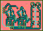
I will modify the current board to connect it to the DUE.

It means I will cut off the BOARDUINO part.

When it is finished, I will post it on this thread.


OldNo7

0
Joined
Nov 13, 2012
Messages
79
Points
8
If your just driving an LED wouldn't it be easier to use a transistor?
 

Attachments

  • screencapture.jpg
    screencapture.jpg
    5.6 KB · Views: 411

camvo

0
Joined
Sep 25, 2011
Messages
102
Points
0
Yes OldNo7.

Why would you want to drive something as simple as a LED with a DAC??

Overkill!!
 
Last edited:
Joined
Feb 10, 2012
Messages
330
Points
0
If your just driving an LED wouldn't it be easier to use a transistor?

I think the comment BB made was regarding users who have driven a LED with the DAC pin and damaging the OP.

Canvo is not doing this, he is using the DAC to drive the scanner signal and an opamp would give some additional buffering protection:beer:

That circuit showing the transistor needs a current limiting resistor in series with the LED;)

ATB
MM
 

OldNo7

0
Joined
Nov 13, 2012
Messages
79
Points
8
I understand he's making a DAC for the galvos. My mind just jumped ahead to the TTL modulation. I should have explained that. Sorry, it was early Monday morning and I was at the lake all weekend. :tired:

Now, after thinking about it you really only need a pull-down resistor for TTL.

@camvo I'm glad your taking the time to do this. I'm excited to see what turns out.
 

camvo

0
Joined
Sep 25, 2011
Messages
102
Points
0
I finished designing the PCB. Sneak preview in the attachment. (Pink color is copper fill areas.)

I have made it shield style so you can just snap it on your DUE.
So no wiring. And you can free your DUE for other projects when desired in a matter of seconds.
(Oops...the salesman in me popped up.)

The board will have TTL blanking only.


The previous version which I made had no pull down resistors on the blanking pins OldNo7 and it worked fine.
(See in the first few posts the results.)

I will first actually make the board and test it. Then brag about it. :)
After that I will publish the final version for anyone interested.


(Still waiting for the new power supply for the RGB laser.) :mad:

.
 

Attachments

  • PCB-GALVO-DUE-SHIELD.PNG
    PCB-GALVO-DUE-SHIELD.PNG
    60.6 KB · Views: 1,325
Last edited:
Joined
Feb 10, 2012
Messages
330
Points
0
I finished designing the PCB. Sneak preview in the attachment. (Pink color is copper fill areas.)
I will first actually make the board and test it. Then brag about it. :)
After that I will publish the final version for anyone interested.
(Still waiting for the new power supply for the RGB laser.) :mad:
.

Hi Camvo,

Looks good, I need a correction board, so I'd be interested in seeing the final result. Hope you get the PSU soon (want to see that RGB beam:beer:).

I've been thinking about the 328 and if I can squeeze any more out of it.
The SPI is running at the moment at 4mhz and this can be adjusted to run up to the full clock frequency by this command SPI_CLOCK_DIV2 (this would give me 8mhz.)

I'm not sure if this will free up the processor much as the data is handled by the SPI hardware. However IF the processor is waiting for the hardware to finish, then it could potentially save a lot of time.
I'll try it later.

(I have a Raspberry Pi SBC, this runs with a 700mHz Arm processor - just to be different, I might give that a go, but I'll be back at the bottom of the learning curve!
It's about £30 so is a good price to performance ratio).

ATB
MM
 

camvo

0
Joined
Sep 25, 2011
Messages
102
Points
0
That is also why I decided to use the ARDUINO DUE.
I know nothing about the programming the Raspberry Pi.


The board basically would do the correction of any DAC 0~+5V.
So also the DAC output of a RB-PI.

I etched the PCB yesterday evening so I hope before the end of the weekend, to get things running.
 
Joined
Feb 10, 2012
Messages
330
Points
0
Well,.... the SPI going from 4mhz to 8mHz increased the speed from 13.6Kpps to 14.6Kpps.
Bit dissapointing:(

Next step, might try some Rasberry Pi.
 

camvo

0
Joined
Sep 25, 2011
Messages
102
Points
0
Hi guys,


Well, I finished the shield and it works. (OMG!!) :beer:
There was a minor error in the PCB but it was easy to fix it.

I could not test the blanking because I am still waiting for the RGB power supply.
Once I got that in, I will hook it up.


And...as I promised in the begining of this thread, the PCB-Layout is attached. For Free!!!!
(the corrected version.)

I attached some images and movie of the results.

If you want to open the PCB, you have to download DESIGNSPARK

It is free sofware but you will need it to print the PCB mask if you want to make you own shield.
 

Attachments

  • SHIELD ON THE DUE TOP.jpg
    SHIELD ON THE DUE TOP.jpg
    353.6 KB · Views: 1,149
  • SHIELD ON THE DUE BOTTOM.jpg
    SHIELD ON THE DUE BOTTOM.jpg
    337.1 KB · Views: 1,115
  • DUE SHIELD DETAIL TOP.jpg
    DUE SHIELD DETAIL TOP.jpg
    340.8 KB · Views: 1,387
  • DUE SHIELD DETAIL BOTTOM.jpg
    DUE SHIELD DETAIL BOTTOM.jpg
    404.8 KB · Views: 582
  • WAVES FROM SHIELD.jpg
    WAVES FROM SHIELD.jpg
    307.3 KB · Views: 2,799
  • SINE WAVE 50pts-1cycle from shield.wmv
    5.7 MB · Views: 286
  • DUE SHIELD LAYOUT.PNG
    DUE SHIELD LAYOUT.PNG
    60.7 KB · Views: 797
  • ILDA ARDUINO DUE.zip
    20.7 KB · Views: 288
Last edited:

camvo

0
Joined
Sep 25, 2011
Messages
102
Points
0
I did some more programming on the shield.

I added a MOSFET transisitor (BUK555) to create blanking.

I created a dash-dot line and it is possible to rotate the line it around its center.

No flickering and smoothly.

So far, so good!!!

Below the code:


Code:
int grad     = 0;
float rad    = 0;
float pi     = 3.14;

int blanking = 46;     //laser blanking pin

int valx     = 2040;   // set x to center
int valy     = 2040;   // set y to center
int valxc    = 0;      // set x to center
int valyc    = 0;      // set y to center
int midx     = 2040;   // master center for x
int midy     = 2040;   // master center for y

int k        = 0;      // position in imdata aray
int step     = 1;      // rotation speed
int zoom     = 3;      // size of image

int points   = 31;      // number of points in the image

int imgdata [250] =
    {
     0,  -600,  0,	   
     1,  -600,  0,
     0,  -600,  0,
     0,  -500,  0,	   
     1,  -500,  0,	   
     1,  -400,  0,
     0,  -300,  0,
     1,  -300,  0,	   
     0,  -300,  0,
     0,  -200,  0,	   
     1,  -200,  0,	   
     1,  -100,  0,	   
     0,  -100,  0,
     0,     0,  0,
     1,     0,  0,
     0,     0,  0, 
     0,   100,  0,
     1,   100,  0,
     1,   200,  0,
     0,   200,  0,
     0,   300,  0,
     1,   300,  0, 
     0,   300,  0, 
     0,   400,  0,
     1,   400,  0,  
     1,   500,  0,	     
     0,   500,  0,	   
     0,   600,  0,   
     1,   600,  0,
     0,   600,  0,
    };
 
void setup()   

{                
 pinMode(blanking, OUTPUT);
 pinMode(DAC0, OUTPUT); 
 pinMode(DAC1, OUTPUT); 
 analogWriteResolution(12);  
 
} // end void setup

void loop() 
{
 for (int grad = 0; grad < 360; grad=grad+step)
     {
      float rad = 2*pi * (grad/360.0);
      for (k = 0; k < points*3; k++)  
          {   
           if (imgdata[k] == 0)                // laser ON/OFF
              {
               digitalWrite(blanking, LOW);    //turn off laser
              }
              else
              {
               digitalWrite(blanking, HIGH);   //turn laser on
              }
 
          k = k + 1;                          //inc counter to index to x coord
          valx  = imgdata[k];                 //pick up the x-coordinate from the image data array
          valxc = imgdata[k];                 //make a copy for the rotation calculation
          k = k + 1;                          //inc counter to index to Y coord
          valy  = imgdata[k];                 //pick up the y-coordinate from the image data array
          valyc = imgdata[k];                 //make a copy for the rotation calculation
 
          valx = valxc * cos(rad) - valyc * sin(rad);
          valy = valxc * sin(rad) + valyc * cos(rad);  
      
          //output x & y co-ord
          analogWrite(DAC1, valx * zoom + midx);
          analogWrite(DAC0, valy * zoom + midy);  

          delay(1);
          //delayMicroseconds(750);        // pauses for 10 microseconds  
         }     
       }
} // end void loop


//(x,y)---->(x*Cos(°)-y*Sin(°), x*Sin(°)+y*Cos(°)
 

Attachments

  • ROTATING DASH DOT LINE.wmv
    14.1 MB · Views: 266
Joined
Oct 26, 2007
Messages
5,438
Points
83
Looks good. It's nice not having to worry that some floating point calculations are going to kill your frame rates huh?
 

camvo

0
Joined
Sep 25, 2011
Messages
102
Points
0
Thanks guys,

I will post a new movie as soon as I get the power supply of the RGB laser.
 
Last edited:

camvo

0
Joined
Sep 25, 2011
Messages
102
Points
0
FINALLY!!!

The new power supply of the RGB came in today.

I implemented the RGB blanking on the code.

Have a look at the results.


Here is the code I used:

Code:
int grad     = 0;
float rad    = 0;
float pi     = 3.14;


int lred      = 50;    // blanking pin red
int lgreen    = 46;    // blanking pin green
int lblue     = 42;    // blanking pin blue

int valx     = 2040;   // set x to center
int valy     = 2040;   // set y to center
int valxc    = 0;      // copy of valx for the rotation formula
int valyc    = 0;      // copy of valy for the rotation formula
int midx     = 2040;   // master center for x
int midy     = 2040;   // master center for y

int k        = 0;      // position in imdata aray
int step     = 1;      // rotation speed
int zoom     = 3;      // size of image

int points   = 24;      // number of points in the image

// image data
int imgdata [250] =
    {
     0,   200,   200,	   
     1,   200,   200,
     1,   400,   200,
     1,   400,   400,	   
     1,   200,   400,	
     1,   200,   200,
     0,  -400,   200,
     2,  -400,   200,
     2,  -200,   200,	   
     2,  -200,   400,
     2,  -400,   400,
     2,	 -400,   200,
     0,  -400,  -400,	   
     3,  -400,  -400,	   
     3,  -200,  -400,
     3,  -200,  -200,
     3,  -400,  -200,
     3,  -400,  -400,
     0,   200,  -400, 
     4,   200,  -400,
     4,   400,  -400,
     4,   400,  -200,
     4,   200,  -200,
     4,   200,  -400,
    };
 
void setup()   

{                
 pinMode(lred,   OUTPUT);
 pinMode(lgreen, OUTPUT); 
 pinMode(lblue,  OUTPUT);
 
 pinMode(DAC0,  OUTPUT); 
 pinMode(DAC1,  OUTPUT); 
 
 analogWriteResolution(12);  
 digitalWrite(lred,   LOW);    //turn off laser
 digitalWrite(lgreen, LOW);    //turn off laser
 digitalWrite(lblue,  LOW);    //turn off laser
} // end void setup

void loop() 
{
 for (int grad = 0; grad < 360; grad=grad+step)
     {
      float rad = 2*pi * (grad/360.0);
      for (k = 0; k < points*3; k++)  
          {   
           switch (imgdata[k]) 
             {
              case 0:
                black();
                break;
              case 1:
                red();
                break;
              case 2:
                green();
                break;
              case 3:
                blue();
                break;
              case 4:
                white();
                break;
              case 5:
                turq();
                break;
              case 6:
                yellow();
                break;
              case 7:
                lila();
                break;
              default: 
                black(); // just to be safe    
             }

          k = k + 1;                          //inc counter to index to x coord
          valx  = imgdata[k];                 //pick up the x-coordinate from the image data array
          valxc = imgdata[k];                 //make a copy for the rotation calculation
          k = k + 1;                          //inc counter to index to Y coord
          valy  = imgdata[k];                 //pick up the y-coordinate from the image data array
          valyc = imgdata[k];                 //make a copy for the rotation calculation
 
          valx = valxc * cos(rad) - valyc * sin(rad);
          valy = valxc * sin(rad) + valyc * cos(rad);  
      
          //output x & y co-ord
          analogWrite(DAC1, valx * zoom + midx);
          analogWrite(DAC0, valy * zoom + midy);  

          delay(1);                        // pauses for xx miliseconds
          //delayMicroseconds(800);        // pauses for xx microseconds  
         }     
       }
} // end void loop

//(x,y)---->(x*Cos(°)-y*Sin(°), x*Sin(°)+y*Cos(°)

void black()  // color 0
{
 digitalWrite(lred,   LOW);
 digitalWrite(lgreen, LOW);
 digitalWrite(lblue,  LOW);  
}

void red()    // color 1
{
 digitalWrite(lred,   HIGH);
 digitalWrite(lgreen,  LOW);
 digitalWrite(lblue,   LOW);
} 
 
void green()  // color 2  
{
 digitalWrite(lred,    LOW);
 digitalWrite(lgreen, HIGH);
 digitalWrite(lblue,   LOW);
}

void blue()   // color 3
{
 digitalWrite(lred,    LOW);
 digitalWrite(lgreen,  LOW);
 digitalWrite(lblue,  HIGH);
}

void white()  // color 4
{
 digitalWrite(lred,   HIGH);
 digitalWrite(lgreen, HIGH);
 digitalWrite(lblue,  HIGH);
}

void turq()   // color 5
{
 digitalWrite(lred,    LOW);
 digitalWrite(lgreen, HIGH);
 digitalWrite(lblue,  HIGH);
}

void yellow() // color 6 
{
 digitalWrite(lred,   HIGH);
 digitalWrite(lgreen, HIGH);
 digitalWrite(lblue,   LOW);
}

void lila()   // color 7
{
 digitalWrite(lred,   HIGH);
 digitalWrite(lgreen,  LOW);
 digitalWrite(lblue,  HIGH);
}
 
Joined
Oct 26, 2007
Messages
5,438
Points
83
Looks good! Nice and smooth!

You should try benchmarking the system to see how many points you can push out.


Top