Welcome to Laser Pointer Forums - discuss green laser pointers, blue laser pointers, and all types of lasers

LPF Donation via Stripe | LPF Donation - Other Methods

Links below open in new window

ArcticMyst Security by Avery

ARDUINO & DAC for XY projector

OldNo7

0
Joined
Nov 13, 2012
Messages
79
Points
8
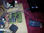
It looks like this implementation has the LDAC pin tied to ground therefore it'll write the value as soon as it's recieved. What you want to do it tie the LDAC pin to one of the arduino pins (probably should have a pull up resistor) write the x value, write the y value then set LDAC low. If you have more than 1 DAC (analog modulation) you could tie both LDAC pins to the same arduino pin.

Code:
/*
  MCP4922 test
  outputs steadily rising voltages through both DACs
  
  Steve Woodward, 2010
  most code borrowed from
  http://mrbook.org/blog/2008/11/22/controlling-a-gakken-sx-150-synth-with-arduino/
  
  connections
  ====================================================
  
  +5v           > 4922 pin 1
  Ard pin 10    > 4922 pin 3   (SS - slave select)
  Ard pin 13    > 4922 pin 4   (SCK - clock)
  Ard pin 11    > 4922 pin 5   (MOSI - data out)
  Ard pin 9     > 4922 pin 8   (LDAC)
  +5v           > 4922 pin 11  (voltage ref DAC B)
  Ground        > 4922 pin 12
  +5v           > 4922 pin 13  (voltage ref DAC A)
 
 
  4922 pin 14 DAC A > 1k resistor > synth CV in
  
 */
 
 
// MCP4922 DAC out
#define DATAOUT 11//MOSI
#define DATAIN 12//MISO - not used, but part of builtin SPI
#define SPICLOCK  13//sck
#define SLAVESELECT0 10//ss
#define LDAC 09
 
int i = 0;
 
void setup() {
  SPI_setup();
  Serial.begin(9600);
}
 
void loop() {
 i++;
 Serial.println(i);
 write_note(i);
 if(i>=4096) {
  i=0; 
 }
}
 
void write_note(int i) {
  write_valueY(i);
  write_valueX(i);
  digitalWrite(LDAC,LOW); // move values from buffer to output
  int i=100;              // LDAC needs to be held low for 20ns. Using a 
  while(i--);             // scope and adjust the value of i 
  digitalWrite(LDAC,HIGH); 
}


// **************************************************
// SPI for DAC
 
void SPI_setup(){
 
  byte clr;
  pinMode(DATAOUT, OUTPUT);
  pinMode(SPICLOCK,OUTPUT);
  pinMode(SLAVESELECT0,OUTPUT);
  pinMode(LDAC,OUTPUT);
  digitalWrite(SLAVESELECT0,HIGH); //disable device
  digitalWrite(LDAC,HIGH); //disable device
 
  SPCR = (1<<SPE)|(1<<MSTR) | (0<<SPR1) | (0<<SPR0);
  clr=SPSR;
  clr=SPDR;
  delay(10);
}
 
// write out through DAC A
void write_valueX(int sample)
{
  // splits int sample in to two bytes
  byte dacSPI0 = 0;
  byte dacSPI1 = 0;
  dacSPI0 = (sample >> 8) & 0x00FF; //byte0 = takes bit 15 - 12
  dacSPI0 |= (1 << 7);    // A/B: DACa or DACb - Forces 7th bit  of    x to be 1. all other bits left alone.
  dacSPI0 |= 0x10;
  dacSPI1 = sample & 0x00FF; //byte1 = takes bit 11 - 0
  dacSPI0 |= (1<<5);  // set gain of 1
  digitalWrite(SLAVESELECT0,LOW);
  SPDR = dacSPI0;			  // Start the transmission
  while (!(SPSR & (1<<SPIF)))     // Wait the end of the transmission
  {
  };
 
  SPDR = dacSPI1;
  while (!(SPSR & (1<<SPIF)))     // Wait the end of the transmission
  {
  };
  digitalWrite(SLAVESELECT0,HIGH);
  //delay(2);
}
 
// write out through DAC B
void write_valueY(int sample)
{
  // splits int sample in to two bytes
  byte dacSPI0 = 0;
  byte dacSPI1 = 0;
  dacSPI0 = (sample >> 8) & 0x00FF; //byte0 = takes bit 15 - 12
  dacSPI0 |= 0x10;
  
  dacSPI1 = sample & 0x00FF; //byte1 = takes bit 11 - 0
  dacSPI0 |= (1<<5);  // set gain of 1
  
  digitalWrite(SLAVESELECT0,LOW);
  SPDR = dacSPI0;			  // Start the transmission
  while (!(SPSR & (1<<SPIF)))     // Wait the end of the transmission
  {
  };
 
 
  SPDR = dacSPI1;
  while (!(SPSR & (1<<SPIF)))     // Wait the end of the transmission
  {
  };
  digitalWrite(SLAVESELECT0,HIGH);
  //delay(2);
}
 
Last edited:


Joined
Oct 26, 2007
Messages
5,438
Points
83
You can also buy SRAMs and use those for extra memory. Overall though, I'd just go buy a Teensy 3.0 or Due and skip the 328. Sure, it's an interesting problem, but it's a lot of diminishing returns. You may end up spending more for the parts to make the inferior chip work, rather than just getting something better to start with.

A better thing to try with these 328s is work on more efficient calculation code. For example, rather than using the floating point library that requires emulation, you could use look-up tables for trig functions, and use fixed-point arithmetic for calculations. That saves many CPU cycles and you can just generate nice effects programmatically.
 
Joined
Feb 1, 2008
Messages
2,894
Points
0
You mean like making a huge list of enumerated types to reference a trig answer without having to actually calculate anything? Even a basic if() condition can take some significant time to express before the condition is determined true or false.

Does anyone know if the Due's uC can be clocked higher? Or is it already maxed?
 
Joined
Feb 10, 2012
Messages
330
Points
0
You can also buy SRAMs and use those for extra memory. Overall though, I'd just go buy a Teensy 3.0 or Due and skip the 328.
A better thing to try with these 328s is work on more efficient calculation code. For example, rather than using the floating point library that requires emulation, you could use look-up tables for trig functions, and use fixed-point arithmetic for calculations. .

Totally agree BB,

I think even with a look up table, the 328 won't have enough grunt.
At the moment, I'm just outputting the points direct from a data table and getting 30 ish Hz with ~500 points.
I think to get a decent graphic, the show guys use a minimum of 700 points (?) which puts the 328 at "full throttle" :D

It's an interesting experiment, but as you suggest a Due / 'mhor power' is the way forward.:beer:

I powered up my G120d last night and got a bit of smoke from the amp card:cryyy:
I'm hoping its just a tant cap that has fizzed - same thing happened a few years ago - new cap fixed it.
Soon as its running, I'll try the G120ds with the 328 just to see what it can do.

ATB
MM

Edit, just noticed a test lable on the back of the galvo amp, dated 1989 - I installed this 24 years ago :)
 
Last edited:
Joined
Oct 26, 2007
Messages
5,438
Points
83
Well for example consider the cosine function in four quadrants:

Q1: cos_1(t) = cos(t) where t in [0, pi/2)
Q2: cos_2(t) = cos(t) where t in [pi/2, pi)
Q3: cos_3(t) = cos(t) where t in [pi, 3pi/2)
Q4: cos_4(t) = cos(t) where t in [3pi/2, 2pi)

There's a lot of symmetry between these four regions. They're basically the same function, but time shifted and sign-adjusted:

- In Q2, cos_2(t) = -cos_1(pi - t)

Ex: cos_2(pi/2) = -cos_1(pi - pi/2) = -cos_1(pi/2) = 0
cos_2(pi) = -cos_1(pi - pi) = -cos_1(0) = -1

- In Q3, cos_3(t) = cos_2(2pi - t) = -cos_1(pi - 2pi + t) = -cos_1(t - pi)

- In Q4, cos_4(t) = cos_1(2pi - t)

All this means you can tabulate only the first quadrant into a look-up table (LUT) and then use a few if-statements to determine how to shift values and choose a sign. Ex:

Code:
static int COS_LUT[] = { // precomputed values for 64 degrees in first quadrant};

// Assuming that input angle is provided from [0, 0xFF] mapping to 0 -> 2pi

#define COS(T)  \
    ((T) < 64) ? COS_LUT[(T)] : \
    ((T) < 128) ? -COS_LUT[127 - (T)] : \
    ((T) < 192) ? -COS_LUT[(T) - 128] : \
    COS_LUT[255 - (T)] 
#define SIN(T)  \
    ((T) < 64) ? COS_LUT[63 - (T)] : \
    ((T) < 128) ? COS_LUT[(T) - 64] : \
    ((T) < 192) ? -COS_LUT[127 - (T)] : \
    -COS_LUT[(T) - 192]

I believe the above is correct and could even be adapted for floating point types. What you lose is having to store 64 precomputed values and adopt a fixed format for representing numbers (a very powerful technique for fast arithmetic). What you gain is not needing to rely on the slow trig functions on processors without a dedicated floating point unit, but instead each calculation requires a maximum of four conditionals, and a simple table look-up. Compare this to the trig functions on the ATmega, where standard trig functions take thousands of cycles to complete. The above LUT-based trig functions have 256 different values around a circle, which is often more than enough for graphics and other stuff. This is easily extended to larger LUTs.

If you want to read up more on fixed point arithmetic and making efficient math functions, check out this site. Also take a look at other fixed point techniques, especially fast approximations, if you want to avoid tables.

You should consider these techniques even for more powerful processors such as the ARMs or any processor without a dedicated FPU. You may have more spare cycles, but floating point operations are still very slow and there are few gains by using them instead of fixed-point type operations and types.
 
Last edited:
Joined
Feb 1, 2008
Messages
2,894
Points
0
Someone tell this man to stop doing coding in the early hours of morning. He's blowing my mind a bit.
 
Joined
Feb 10, 2012
Messages
330
Points
0
Here is a few photos of the "laser show controller:D and my 1980s scan head !

AtMega328, DAC and OLED display
img8168vs.jpg


Dusty G120d scanners - blanking scanner below - no easy peasy TTL blanking control those days:)
img8170y.jpg


GM20 colour changer -
img8171m.jpg


Z blanking beam path - a right PITA to keep aligned
img8172s.jpg


Hope you like the old retro photos :beer:

Photo of the laser running Camvo's software routine but with the DAC LDAC line latching the X & Y output at the same time.
Same number of co-ords (360/10) and the second photo 360/5.

img8186x.jpg


img8188c.jpg


ATB
MM
 
Last edited:

camvo

0
Joined
Sep 25, 2011
Messages
102
Points
0
Hi all,

Well, I tried the ARDUINO DUE tonight but unsuccesfull.

I hacked the previous xy projector to use its galvos.
I connected the DAC0, DAC1 and GND to the DAC correction amplifiers.
I used the ARDUINO 1.5 IDE.

I used the below code, and it does as in the video

Code:
void setup()
{

  pinMode(DAC0, OUTPUT); 
  pinMode(DAC1, OUTPUT); 
  analogWriteResolution(12);  

}

void loop() {

for (int i=0; i<4000; i=i+800)
  {
   analogWrite(DAC0, i);
   delay(500);
   analogWrite(DAC1, i);
   delay(500); 
  }
  
}

This code should produce a diagonal line. The delays are just there to slow everything down so you can see what is happening.
When I put a 1ms delay, the galvos go realy fast.

I looks like it that the DACs are updated one by one (as expected) but the worst part is that while DAC1 is updated, DAC0 is set to 0 and vice versa.

Unless there is something terribly wrong with the code.... :banghead:


UPDATE:
Found this on the ARDUINO Site in the release notes of ARDUINO 1.5.2 IDE

* Fixed analogWrite() on DAC0/1 when writing on both DACs
(thanks to smay4finger)

I will try that tomorrow. Maybe that is the reason.

.
 

Attachments

  • ARDUINO DUE-01.wmv
    3.3 MB · Views: 197
  • DUE SET UP-01.jpg
    DUE SET UP-01.jpg
    430.6 KB · Views: 1,830
  • DUE SET UP-02.jpg
    DUE SET UP-02.jpg
    598.6 KB · Views: 2,764
Last edited:

camvo

0
Joined
Sep 25, 2011
Messages
102
Points
0
I envy your results Multimode!!!!

Lord of the Rings!!!

Can you share the code?
 
Last edited:

camvo

0
Joined
Sep 25, 2011
Messages
102
Points
0
I also tried the MCP4922 DAC and applied the LDAC function.

It worked but way too slow.

I could draw diagonal lines.
2 points and already some flickering.


I used this code:

Code:
/*************************************************************************
**  AH_MCP4922.h - Library for get out analog voltage          	        **
**  Created by A. Hinkel 2012-01-05					**
**  download from "http://www.alhin.de/arduino"  			**
**									**
**  Based on code from website: 					**
**  http://www.sinneb.net/2010/06/mcp4921-12bit-dac-voltage-controller/ **
**									**
**  Released into the public domain.  		                    	**
*************************************************************************/

#include "AH_MCP4922.h"

#define AI1 A1                                  //Analog input monitor 1
#define AI2 A2                                  //Analog input monitor 2

//define AnalogOutput (MOSI_pin, SCK_pin, CS_pin, DAC_x, GAIN) 
//AH_MCP4922 AnalogOutput1(51,52,53,LOW,HIGH);    //define AnalogOutput1 for MEGA_board, select DAC_A, Gain=1x
//AH_MCP4922 AnalogOutput2(51,52,53,HIGH,LOW);    //define AnalogOutput2 for MEGA_board, select DAC_B, Gain=2x

//AH_MCP4922 AnalogOutput1(11,13,12,LOW,HIGH);    //define AnalogOutput1 for UNO_board, select DAC_A, Gain=1x
//AH_MCP4922 AnalogOutput2(11,13,12,HIGH,LOW);    //define AnalogOutput2 for UNO_board, select DAC_B, Gain=2x

AH_MCP4922 AnalogOutput1(11,13,10,LOW,HIGH);     //define AnalogOutput1 for UNO_board, select DAC_A, Gain=1x
AH_MCP4922 AnalogOutput2(11,13,10,HIGH,HIGH);    //define AnalogOutput2 for UNO_board, select DAC_B, Gain=1x


/********************************
*            | MEGA  |  UNO     *
*  --------------------------   *
*  SCK_pin   |  52   |   13     *
*  MOSI_pin  |  51   |   11     *
*  CS_pin    |  53   |   12     *
*********************************
* DAC=LOW  => DAC_A select	*
* DAC=HIGH => DAC_B select	*
*				*
* GAIN=LOW  => 2x gain select	*
* GAIN=HIGH => 1x gain select	*
********************************/

//***************************************************************** 
void setup() { 
  pinMode(4, OUTPUT);       // LDAC
  AnalogOutput1.setValue(0);
  AnalogOutput2.setValue(0);
  digitalWrite(4,HIGH);
} 

//*****************************************************************
void loop() {
 
  for (int i=0; i<4001; i+=2000)
 {
  AnalogOutput1.setValue(i);                     //set voltage for AnalogOutput1 
  AnalogOutput2.setValue(i);                     //set volateg for AnalogOutput2
  digitalWrite(4,LOW);   //update the DAC (LDAC)
  digitalWrite(4,HIGH);
 }
 
}
 
Joined
Feb 10, 2012
Messages
330
Points
0
Can you share the code?

No problem...

Code:
#include <Wire.h>
#include <Adafruit_GFX.h> //OLED lib
#include <Adafruit_SSD1306.h> //OLED lib
#include "SPI.h" // necessary library for DAC


const int OLED_CLK =A5;
const int OLED_MOSI =2;
const int OLED_RESET =A4;
const int OLED_DC =4;
const int OLED_CS =3;
Adafruit_SSD1306 display(OLED_MOSI, OLED_CLK, OLED_DC, OLED_RESET, OLED_CS);
#define LOGO16_GLCD_HEIGHT 16 
#define LOGO16_GLCD_WIDTH  16 
#if (SSD1306_LCDHEIGHT != 64)
#error("Height incorrect, please fix Adafruit_SSD1306.h!");
#endif


int count=0;
int CS=6;
int LDAC=5;
int times=0;
int grad = 0;
float rad = 0;
float pi = 3.14;
int midx       = 2040;      // master center for x
int midy       = 2040;      // master center for y
int valx  = 2040; // set the x-coordinate to center
int valy  = 2040; // set the x-coordinate to center

int del=0; // used for various delays
word outputValue = 0; // a word is a 16bit number out of a 24bit stream
word dataShift=0;
byte data = 0; // and a byte is an 8-bit number

//const byte WRITEA = 0b00011000;   // writes to A
const byte WRITEA = 0b00000000;   // writes to A
const byte WRITEB = 0b00000001;   // writes to B


void setup()   {                
  Serial.begin(9600);
  
===========Set up OLED ==================
  // by default, we'll generate the high voltage from the 3.3v line internally
  display.begin(SSD1306_SWITCHCAPVCC); // init done
  display.clearDisplay();   // clears the screen and buffer
//====================================

 //set pin(s) to input and output
  pinMode(CS, OUTPUT); //sync DAC chip select
  pinMode(LDAC, OUTPUT); //LDAC 
  SPI.setDataMode(SPI_MODE2); 
  SPI.begin(); // wake up the SPI bus.
  SPI.setBitOrder(MSBFIRST);
  
  pinMode(CS, OUTPUT); 
  pinMode(LDAC, OUTPUT); 

digitalWrite(CS, HIGH); //set DAC Chip select high
digitalWrite(LDAC, HIGH); //set DAC LDAC select high

//===========Set DAC internal VREF to ON==========
    digitalWrite(CS, LOW);//CS low
    data = 0b00111000;//d23 tp D16
    SPI.transfer(data);
    data = 0b00000000; //D8 to D15
    SPI.transfer(data);
    data = 0b00000001;//D0 to D7  LSB to 1 = ref on
    SPI.transfer(data);
    digitalWrite(CS, HIGH);//CS high
//================================================

}

void loop() {
  
  /*
  /====== My OLED for debugging =============
  display.clearDisplay();
  void drawpixel(void);  // draw a single pixel
  display.drawPixel(10, 2, WHITE);
 
  display.setTextSize(2);
  display.setTextColor(WHITE);
  display.setCursor(0,20);
  display.println("Laser Show");
  display.setTextColor(BLACK, WHITE); // 'inverted' text
  count=count+1;
  display.setCursor(30,40);
  display.println(count);
  display.display();
  /==========================================
  */
{


 //=========CAMVO's circle generator ==========
  for (int grad = 0; grad < 360; grad=grad+5)
  {
   float rad = 2*pi * (grad/360.0);
   valx = cos(rad)*2000 + midx;    
   valy = sin(rad)*2000 + midy;
   sendx();
   sendy();
  }
 } //=========== end circle loop=============== 
} //=============End of Void loop==============
   
   
 //===========Send data sub routines============
  void sendx()
{
    digitalWrite(CS, LOW);//CS low
    data=(WRITEA);//sets address and control register for X dac
    SPI.transfer(data);
    dataShift= (valx <<4);
    data = highByte (dataShift);
    SPI.transfer(data);  
    data = lowByte(dataShift);
    SPI.transfer(data);
    digitalWrite(CS, HIGH);//CS high 
}


void sendy()
{
    digitalWrite(CS, LOW);//CS low
    data=(WRITEB);//sets address and control register for Y dac
    SPI.transfer(data);
    dataShift= (valy <<4);
    data = highByte (dataShift);
    SPI.transfer(data);   
    data = lowByte(dataShift);
    SPI.transfer(data); 
    //====now output x & y co-ord
    digitalWrite(LDAC, LOW);//LDAC
    digitalWrite(LDAC, HIGH);//LDAC 
    digitalWrite(CS, HIGH);//CS high 
    
}


ATB
MM
 
Last edited:

camvo

0
Joined
Sep 25, 2011
Messages
102
Points
0
VICTORY!!!!! :drool:


I downloaded the ARDUINO 1.5.2 IDE and uploaded the same code as yesterday to the board.

It works like a charm!!!

So the problem was in the ARDUINO IDE. (Thank God!)

The scanners make the usual noise as if controlled by a show card. Perfect!!!

I used this code to draw a circle

Code:
int grad  = 0;
float rad = 0;
float pi  = 3.14;
int midx  = 2040;   // master center for x
int midy  = 2040;   // master center for y

int valx  = 2040;   // set x to center
int valy  = 2040;   // set y to center

void setup()
{
 pinMode(DAC0, OUTPUT); 
 pinMode(DAC1, OUTPUT); 
 analogWriteResolution(12);  
}

void loop() 
{
 for (int grad = 0; grad < 360; grad=grad+10)
    {
     float rad = 2*pi * (grad/360.0);
     valx = cos(rad)*2000 + midx;    
     valy = sin(rad)*2000 + midy;
     analogWrite(DAC0, valx);
     analogWrite(DAC1, valy);
     //delayMicroseconds(500); 
    }
}

It cannot get any simpler than this I think.
The XY coordinates are calculated on the fly with floating points in it!

When I do not use the "delayMicroseconds(500)", the circle is smooth as a babies butt.

When I use a 500 usec delay, I get the dots in the circle.

This is just what I wanted.

There only go 3 wires to the DAC correction amps. (DAC0, DAC1 and GND)
Next step is to attach the blanking wires but I have to wait for the new power supply of the RGB lasers.

I am happy as a child with a new toy!!
 

Attachments

  • DUE TEST CIRCLE NO DELAY.jpg
    DUE TEST CIRCLE NO DELAY.jpg
    284.2 KB · Views: 2,928
  • DUE TEST CIRCLE NO 500 usec DELAY.jpg
    DUE TEST CIRCLE NO 500 usec DELAY.jpg
    264.7 KB · Views: 1,567
Last edited:
Joined
Feb 10, 2012
Messages
330
Points
0
VICTORY!!!!! :drool:
I am happy as a child with a new toy!!

Congrats !
Glad you got it working :beer:
I think I'll order one of the Due's - looks like a nice board
The 328 with the SPI DAC hasn't got enough guts.

I have been messing with the ILDA test patern, it has 1191 points and the 328 is on its limit. (still very good for such a little processor)
So if I add anything to code the software scan loop it will slow the scan.
The blanking is working with just the 1 red laser, I'd like to add TTL colour control, but I think I'd be wasting my time using the 328 other than an experiment.

How many points can you put in the circle before it starts to flicker?

ATB
MM
 

camvo

0
Joined
Sep 25, 2011
Messages
102
Points
0
I do not know yet Multimode.

I first need to get the rgb power supply. Then I can continue testing.

The laser used in this test setup does not have blanking capacity.
It is a 50mW diode from a cheap stage projector.
Just good enough as a pilot.
 
Joined
Feb 10, 2012
Messages
330
Points
0

camvo

0
Joined
Sep 25, 2011
Messages
102
Points
0
Hi MP,


I bought this one

This laser burned the paint of the door.

Unfortunately the power supply broke down after about 2 hours operation. :yabbmad:

They will send me a new one so the problem is solved as far as I am concerned. :yh:


Top