Welcome to Laser Pointer Forums - discuss green laser pointers, blue laser pointers, and all types of lasers

LPF Donation via Stripe | LPF Donation - Other Methods

Links below open in new window

ArcticMyst Security by Avery

2 Mirror Spiro in a cute box

Morgan

0
Joined
Feb 5, 2009
Messages
2,174
Points
0
Say hello to my little friend....

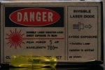
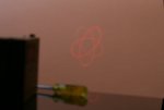
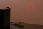
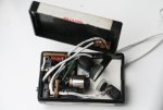
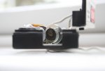
I was given this box and decided to make a Spiro projector out of it mainly because I thought the graphics would look cool. No mistaking what it is! I dumped the 780nm, 5mW diode and put a LPC-815, long-open-can in instead, (after making the red diode from a PHR sled go pop!). I haven't measured the ampage as I am only running this just above lasing threshold.

Just a couple of pics to start with but I'll post more if anyone's interested.

Your opinions are welcomed, good or bad!

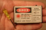
Took a while to build as there were a few hurdles to get over but for a first project, I'm pretty happy. Total build cost was about £30.

Thanks,

M ;)
 

Attachments

  • DPP_0053_001.JPG
    DPP_0053_001.JPG
    211.4 KB · Views: 243


Morgan

0
Joined
Feb 5, 2009
Messages
2,174
Points
0
... 5 lobes...
 

Attachments

  • DPP_0064.JPG
    DPP_0064.JPG
    150.6 KB · Views: 204

Morgan

0
Joined
Feb 5, 2009
Messages
2,174
Points
0
... 7 lobes...
 

Attachments

  • DPP_0070.JPG
    DPP_0070.JPG
    149 KB · Views: 172
Joined
Jul 24, 2007
Messages
2,749
Points
0
:) Good fun aren't they? Get yourself some 1N4001 diode and make a test load then you can wind up the power on that laser ;)
Do you have any pictures of the build in progress?

Regards rog8811
 

Morgan

0
Joined
Feb 5, 2009
Messages
2,174
Points
0
Hi Rog,

I have but I'll show you this one first...

I was a bit creative with my photos. ;)

I think this should illustrate why there were,"... a few hurdles", to overcome...

Enjoy, there will be more of this sort of thing...

;D
 

Attachments

  • DPP_0076.JPG
    DPP_0076.JPG
    195.8 KB · Views: 206
Joined
Dec 26, 2007
Messages
6,129
Points
0
Morgan said:
Hi Rog,

I have but I'll show you this one first...

I was a bit creative with my photos.   ;)

I think this should illustrate why there were,"... a few hurdles", to overcome...

Enjoy, there will be more of this sort of thing...

;D


Oh wow, I didn't think it was this small until I saw that last pic!
 

Morgan

0
Joined
Feb 5, 2009
Messages
2,174
Points
0
Size is everything so I've been told...  ;D

I thought it would be entertaining to present it as a larger build so thanks for sticking with it. (I wasn't sure if the pics were convincing enough but that screwdriver really did the trick!  ;))

Now the cat's out of the bag I'll show you what's inside the box...


This project was inspired by one of the first builds I ever saw. Some may not be surprised that it was one of rog8811's. It was a green laserpen style build that is somewhere on this site and has a great video tutorial. I have to apologise for not documenting the build as well as others have as this thing kind of evolved.

It started as a container for a 9mm diode, (properties as described on the outside of the box), and it was donated by a guy from a nearby photo-repro company who I'd rocked up to asking for free stuff. I knew next to nothing about lasers at that point and was grateful for any bits to play with. I soon realised though that a 780nm, 5mW diode was not going to be of much use to make anything visible but thought it came in a pretty cool box.

After seeing Rog's clear tutorial, I thought I'd try a small scale projector. (Note to newbies: spend some time looking for this, and other, tutorials from rog8811. They are top notch! Friendly, well presented and informative. ;))

The challenge I set myself was to build a two mirror spirograph projector into a box that would run from a mobile phone battery. (At this stage money was tight and I knew nothing about CR123s or anything regards popular power sources.) I also set myself the task of using the diode box AND having the spiro coming out in the direction of the graphic on the box.

Bits used:

1 x LM317T current regulator, (circuit from this site, parts from Rapid Electronics)
1 x RCKSTR driver, (from Stonetek)
2 x SPDT switches, (from Maplins)
1 x Long-can-open diode, (harvested from a LPC-815 sled)
1 x Aixiz module, (from Stonetek)
2 x scavenged mobile phone vibrate motors, (the key to small spiros, I think  ;))
2 x FS mirrors, (from EdmundOptics. 1 x 7.5mm, 1 x 12mm. Both too big!!!)
1 x Ericsson mobile phone, (pics will be updated)

So I guess you want to see the guts of this thing? I'm aware that it ain't the prettiest soldering in the world but this is a work in progress. I also intend to make a bit more room inside by using a smaller driver and re-arranging the LM317T circuit to be more practical, (I had to chop it in half and run a wire just to fit it in there!).

No doubt I will edit this thread to make things clearer and answer possible questions but for now...

... I give you, "The Ericsson Piggy-Back"

I look forward to your approval

M :)
 

Attachments

  • DPP_0034.JPG
    DPP_0034.JPG
    153.7 KB · Views: 221
Joined
Dec 26, 2007
Messages
6,129
Points
0
You have my approval, it's a very tight fit! The resistor looks like crying for help :p

Chuck_Norris_Approved.png


Why the sony ericsson? Is that an old cellphone enclosure? It doesn't seem to be a mobile phone :-?


Oh, I have some ideas about making it cleaner and saving some space, but as I keep thinking about it, no matter how much space you try to save here, the enclosure will maintain its size, so I wouldn't touch it (unless you want to improve the soldering, which for the motors is just fine).


Good work man, welcome to the forum :)
 

Morgan

0
Joined
Feb 5, 2009
Messages
2,174
Points
0
^Thanks Niko. I want to make more room because I'd like to put some pots in to control the motor speed. Because of their size the speed varies slightly which gives a nice variety of shapes but it's a bit random.

The Ericsson is not actually in any of the shots. As you can see, there is no battery in the enclosure. This is because the battery is external and is about the same plan size as the box itself! The idea is that the box sits on the back of the phone. That photo is missing right now but will appear soon.

A note about the motors; I built a jig that would ensure the spindles of both motors would be at the same height and parallel to the base. This was important and no doubt saved time when it came to aligning the mirrors as then I only had one plane to worry about.

Thanks again,

M :)
 

Attachments

  • DPP_0035.JPG
    DPP_0035.JPG
    118.5 KB · Views: 235
Joined
Jul 24, 2007
Messages
2,749
Points
0
That is very tidy, I like small :).... as you will see when I post my next build.... ::)
I'd like to put some pots in to control the motor speed
You only need 1 pot, for the second mirror, all the first mirror does is to provide a circle so slowing it will have no effect.

Regards rog8811 ( and thanks for the compliments!)
 

Morgan

0
Joined
Feb 5, 2009
Messages
2,174
Points
0
rog8811 said:
That is very tidy, I like small :).... as you will see when I post my next build.... ::)

Thank you very much... And I can't wait to see more of your builds.

I'd like to put some pots in to control the motor speed
You only need 1 pot, for the second mirror, all the first mirror does is to provide a circle so slowing it will have no effect.

True enough. In fact, I think now that it has been built, it won't be long before I'm tearing it all out to build it better. Now I KNOW it's possible, I can give it, "a bit of polish". And learning from my mistakes will only improve the finish. (After blowing up your first LD, you don't want to be soldering an Aixiz mounted diode on to a driver that's already fixed into the box! It is not easy and you will burn yourself!! ::))

Regards rog8811 ( and thanks for the compliments!)

My pleasure! :)

I'll try and draw out a schematic of the electrics, as I am sure it is not the most efficient and I'd appreciate some help with the figures.

Thanks for your compliments too !! ;D

M :)
 
Joined
Jan 12, 2008
Messages
3,290
Points
83
Wow your hand is huge! :eek: ::)


Actually, two pots do make a difference. With one pot you either get star or flower patterns. With two pots you'll get both. ;)

Edit:
And if you add a DPDT-switch to one of the motors you can invert the patterns. Really it depends on how much work you want to put on it.
 

Morgan

0
Joined
Feb 5, 2009
Messages
2,174
Points
0
FireMyLaser said:
Wow your hand is huge! :eek: ::)


Actually, two pots do make a difference. With one pot you either get star or flower patterns. With two pots you'll get both. ;)

Edit:
And if you add a DPDT-switch to one of the motors you can invert the patterns. Really it depends on how much work you want to put on it.

You should hear me clap!!! ;D

Stars and flowers eh? I'll consider that for the remodelling.

Definitely do the switches thing as this will gain function for least space sacrificed.

Think I need to nail my maths first!

M :)
 

Morgan

0
Joined
Feb 5, 2009
Messages
2,174
Points
0
... Okay, so below is a quick sketch of the schematics inside the box, (I like pencil and paper ;D)

This is where I'm fully expecting my knowledge to let me down!

I'd appreciate your input to let me know where I've gone wrong and suggestions for improvement. I was hoping for more from the LD but it is pretty dim, (cheap keyring pointer dim! :(). Losses to the drivers perhaps?

I await your wisdom...

M :)

edit: What the hell does, "rofl", mean?   :-? Any other acronyms I should know???  ;D
 

Attachments

  • DPP_0078.JPG
    DPP_0078.JPG
    159.5 KB · Views: 208
Joined
Dec 26, 2007
Messages
6,129
Points
0
You only need 1 pot, for the second mirror, all the first mirror does is to provide a circle so slowing it will have no effect.

Having two pots in my spirograph does make a difference, I can see shapes I can't create with only one pot, they're weird shapes, like artifacts, but they're different.

However, in this project I think you should listen to rog and just use one pot, maybe one little surface mount one that you can turn with the screwdriver...

If you wanted a bigger sized one you could place it right below the diode and to the left of the bottom motor (and stick the dial outside of the enclosure, it won't be pretty but it could be an easy way to do the mod).
 
Joined
Jul 24, 2007
Messages
2,749
Points
0
As per PM, there is not enough input voltage to run the regulator for the Rkcstr or the LM317 motor drive.

If you just connect 7.2 volts to that you would suddenly get a much better laser output. (assuming you set the rkcstr up correctly in the first place).

Regards rog8811


Top