yobresal
0
- Joined
- Nov 5, 2007
- Messages
- 4,919
- Points
- 83
Got one 100mW today. It sucks. 40mW. In the garbage now. At least it didn't mode hop. I have 3 more on the way.


In the garbage??
Does that mean that it died already?
Jay
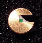
 Also excess flux all over and bubbling-up from some joints - appears board was not cleaned/de-fluxed after soldering? ) Not sure if this is fixable or not.
Great review of the build!
Great review!
Many thanks SEOGUY, that was a very insightful review.
Somehow, I have a feeling i'll be using a lot of 99% Isopropanol, acetone and CCl4 when theshipment arrives.
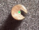
Be careful!The beam was horribly off center and blocked by the module, so I fixed it.
Output climbed to 154mW.
Then the damned thing died before I finished testing.
Awaiting autopsy.
Watch the amount of voltage you pump into these
Oh- and one more comment... DX shipped mine (along with all the other goodies I ordered) in a deflated bubble wrap envelope. The module was in a plastic bag with no other cushion. I'm surprised nothing was knocked loose or broken when I got it.
Beam quality was surprisingly good: stable TEM00, not many artifacts... just poor alignment.
Disassemble the module and apply some thermal adhesive (if you have some silicone or arctic silver glue) around the crystals. They are glued above the diode with not much brass to keep 'em cool.
I'm surprised I got the amount of power out of the (tiny) crystals that I did


 They could be running a 1W at well below full power:thinking:, or perhaps...
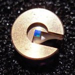
Mine arrived yesterday - cold solder joints, one pin of the laser diode had broken free due to the cold solder joint.
Still no dice, diode is blown open circuit.