Welcome to Laser Pointer Forums - discuss green laser pointers, blue laser pointers, and all types of lasers

LPF Donation via Stripe | LPF Donation - Other Methods

Links below open in new window

ArcticMyst Security by Avery

New DX Green MODULES

alx

0
Joined
Jan 8, 2009
Messages
229
Points
0
I got answer from DX: "Sorry that we have checked both of the items are out of stock, would you like to change to other item? if you do not want to change,you can also ask us for a refund."

I asked now about 30mw and 50mw version! Let see if are still considered "unstable market supply" too and they are intending to retract it from the market...

Regards,
Alx

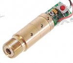
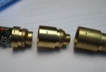
...and today my 10mw modules has been shipped. Also, I already received 200mw module ordered last month and done some measurements (power, voltage, current). I will post here results soon.

Regards,
Alx
 
Last edited:


alx

0
Joined
Jan 8, 2009
Messages
229
Points
0
All right, let's clean up the mess and clarify some things... about DX 200mw green modules...

First, I will upload some photos (from this thread) of this module to show you how I will refer here all its parts. I Numbered 1, 2 and 3!
 

Attachments

  • NewDXModule1-aaaa.jpg
    NewDXModule1-aaaa.jpg
    66.4 KB · Views: 260
  • grnDXlaser11111.jpg
    grnDXlaser11111.jpg
    94.6 KB · Views: 278
Last edited:

alx

0
Joined
Jan 8, 2009
Messages
229
Points
0
First test: entire module, powered from 3V power bench supply using original driver.

Measured current: I=505mA, LPM has been set at 532nm and measured Optical Power using Coherent Lasercheck LPM has been 60-97mw. Is starting from 60mw, after 10-15s goes up to 118mw and after 5-10s goes down to 97mw. The output current is not stable, still trying to increase ... Changing LPM to 808nm i got 8.8mw, and at 1064nm measured power was 37mw. So, in all cases, we measured mixed power (Green+IR).

Lpm set at 532nm -> 97mw (mixed green + IR)
Lpm set at 808nm -> 8.8mw
Lpm set at 1064nm -> 37mw

I repeated test, adding an IR filter (attenuantion factor 10^5 on 1064nm and 10^3 on 808nm) between laser module and my LPM. Here are results:

Lpm set at 532nm -> 41.5mw (true green, maybe a little bit more because some energy is lost when is crossing the filter)
Lpm set at 808nm -> 3.2mw
Lpm set at 1064nm -> 12.2mw
 
Last edited:

alx

0
Joined
Jan 8, 2009
Messages
229
Points
0
Second test: removed 3rd piece in my picture above. U=3V (same as above)

Lpm set at 532nm:
312mw without IR filter (mixed green + IR), 55mw with IR filter (green only)

Lpm set at 808nm:
25mw without IR filter, 4.3mw with IR filter

Lpm set at 1064nm:
100mw without IR filter, 18.6mw with IR filter

Third test: removed also 2nd piece too. U=3V


Lpm set at 532nm:
985mw without IR filter (mixed green + IR), 47.7mw with IR filter (green only)

Lpm set at 808nm:
70.8mw without IR filter, 3.9mw with IR filter

Lpm set at 1064nm:
425mw without IR filter, 6.85mw with IR filter

So, on oll 3 cases above when I used IR filter on 532nm, I got an output around 50mW.

Probably, is a good aproximation to say that if powered from 3V, this module produce 50mW true green!

Important: Due to my post #189 on next page, conclusion above should be reformulated as following:
"If powered from:
- 2.3V, this module produce around 50mW true green!
- 2.7V/570mA (optimal), this module produce around 75mW true green!
- anything above 2.7V up to 3.4V will increase just the heat and will not increase the output power"
 
Last edited:

alx

0
Joined
Jan 8, 2009
Messages
229
Points
0
So, after first 3 tests I concluded that something is going wrong. Driver is not perform well, not regulating current.

Scenario: Original module reassembled (all pieces together), power bench supply, varying input voltage with 0.1V increments(Uin). Started from 3V (catalog data). Measured current (Ild) and optical output power (PO) at 532nm.

Uin(V)--------Ild(mA)---------PO(mW)
3 508 118 (first goes up to 118 in 15-20s, after falling down to 80-90)
2.9 460 104 (not stable)
2.8 421 87.1 (not stable)
2.7 380 70.1 (not stable)
2.6 338 52.2 (not stable)
2.5 279 31.6 (not stable)
2.4 225 16.5 (not stable)

So here we are on a wrong way...It cannot work with voltage under (or up to) 3V...regulator is not regulating ...current very unstable (all the time is trying to increase)... power very unstable too... Does it mean that we need more voltage. Let's see ...

Uin(V)--------Ild(mA)---------PO(mW)
3.1 518 105 (with a peak at 127, after goes down, still unstable)
3.2 536 122 (almost stable)
3.3 555 136 (stable, but current still increasing slower)
3.4 568 153 (stable power for 10-15 secs, after, down to 120mw)
3.5 570 141 (psssst... current increasing only 2mA, so is almost stable around 570mA)
3.6 572 140 (yes, we found stable value)
3.7 572 142 (stable current, stable output)
3.8 572 142
3.9 572 142
4.0 572 140 (some minor deprecation on output)
4.1 572 140
4.2 572 137 (some more but still minor deprecation on output)

Some conclusions:
- driver isnt so bad...
- working voltage: over 3V up to 4.2V, does it mean....18640 LI-Ion Accumulator...
- diode/driver will not have problems if you are powering with max 4.2V (still safe)
- ideal voltage is 3.5V (will not produce unuseful heat)
- REGULATED CURRENT is 572mA
- Output become stable after 10-15 seconds from startup at 572mA for 140mW output average. remain at this value more than 20-30seconds... After that, I can feel the heat and power start decreasing

So, forget about batteries. Use only one LI-Ion cell (bigger capacity).

Important: read post #189 on next page (I adjusted above voltage values due to test equipment wires resistance)
 
Last edited:

alx

0
Joined
Jan 8, 2009
Messages
229
Points
0
All right, now we know for sure: 3.5V/572mA/140mW ...but why output not stable for long time?

Not sure but i think that:
- additional heatsink will help to keep LD as cool as possible
- driver problems related to heat dissipation: the big resistor is closer to D882 transistor and will heat it more than enough to make it unstable

Heat seems to be a real problem. In order to test, I removed 2nd and 3rd piece and point to an object 10m away. After few seconds, I saw on the wall how the shape of spot is changing from round to oval, and after that to.... 2 ovals, and 2 round spots...
Due to heat, LD is changing wavelength, causing this comportment...
Putting 2nd piece in place, become more visible 2 divergent beams... Adding 3rd piece back, the output seems to looks good (only one beem, super nice spot, etc), buuut...if you are looking carefully, booth beams are still there... better collimated...
 
Last edited:

alx

0
Joined
Jan 8, 2009
Messages
229
Points
0
IR diode inside seems to be 1W or more ... remember? at 3V with 2nd and 3rd piece removed I got 985mw without IR filter after crystal... I repeated the test at 3.5V (determined above to be optimal voltage for these modules).

My LPM (limited to max 1W power) has been setup at 532nm! And start counting and go up in few seconds to 999mw...and after that -:-:- (out of range)... OVER 1W optical power at crystal output!!!

Is time to add some attenuators... Placed back, 2nd piece... Now we have 452mW stable output!!! And by the way: looking in front of this piece, I can see with nacked eye the lens inside and COATINGS! YES, MAGENTA AND BLUE REFLECTIONS....so, no doubt, the 2nd piece is COATED and I think is acting as IR filter too... At this stage, we are loosing more than half of total power...

So, we have 1W++ after crystals, 450mw++ after beam collimator and 120mW++ after focusing lens... Does it mean a 1:10 ratio!

Personally, I don't think that the diode at 570mA is overloaded or overloaded to much. I stressed it more than 1 hour, without much cooling and still resisted and NO DEPRECATION.
 
Last edited:

alx

0
Joined
Jan 8, 2009
Messages
229
Points
0
But it burn? It can burn?

Yes and No!

With all pieces assembled, the answer is no! Buuuut...

If you remove 2nd and 3rd piece... and put a match in front of piece 1 (10cm away) it lit instantly...remember ...over 1w power ;-)

If you remove ONLY 2nd piece, and join directly piece 1 with piece 3, we will have also the same situation.... lit matches 5-10cm away... In this case, the spot will become ugly at long distances than in case 2nd piece is mounted too...but you can lit matches...

Also, I think ...with some minor modifications...we can have also adjustable focus... Why? because i screwed/unscrewed the 3rd piece, and observed that the focus point at 1-2m away, became thin...almost very thin... want to screw more...not possible...I am blocked because fillet on 2nd piece has ended and 3rd piece cannot go more inside...

I said no problem i will screw the lens in front of 3rd piece...Not lucky... seems to be glued...I attached a picture to this post... Did someone has success screwing it inside?
 

Attachments

  • dsc01736fsss.jpg
    dsc01736fsss.jpg
    334.4 KB · Views: 284
Last edited:

alx

0
Joined
Jan 8, 2009
Messages
229
Points
0
And a question:

I saw that are few peoples here owning DX 100mw green modules. I saw that seoguy is driving diode at his 100mw module at 530mA but nowhere I saw how much is the output power?

Can anyone post here results?

Regards,
Alx
 
Last edited:

seoguy

0
Joined
Feb 9, 2009
Messages
263
Points
0
I know all of these tests were risky and some would say I should not have done that

fotonphorces, why do you ask for our advice, if you're just going to ignore it? :rolleyes:

I left the original driver attached and I'm just "touching wires" on the 3 pins...

the laser is still in the same state it was when I first posted

Actually, likely not. Drivers are not meant to have power fed into them BACKWARDS!

There's a VERY good chance you may have killed your original driver with what you just did! :cryyy:

I also found out that this pot never stops spinning in any direction. I've messed with some pots in the past but don't remember having one like this.

Yes, I think I mentioned this earlier. The pot they are using has no stops - NOT a good design choice for a laser driver IMO.

I also got a measurement on the pot before I messed with it.

That corresponds with the voltage readings I was getting on my True 5 module. Unfortunately, the measurement you took does not tell us what the pot was set to.

Did you note-down about where the pot was set to physically before you started messing with it?

I decided to move the pot a little while the laser was on. As soon as it got brighter, I stopped turning it. Then it got dimmer by itself...

The pot on the DIY driver?...

Or the pot on the built-in driver when you were powering it with that?...

Or, I don't even want to think about this...adjusting the pot on the built-in driver, while powering that driver backwards from the DIY driver attached to the laser diode pins?

...and the same steps were repeated with the same results.

It's possible you were pushing the laser diode too hard, and it was overheating, causing the wavelength to shift away from 808nm. The vandate crystal needs to be pumped with 808nm, if the laser diode gets too hot and starts to shift away from that, it will cause the green output to get dimmer.

Sorry but my meter only reads voltage.

Well, it apparently reads resistance also, as you posted a measurement on that? :rolleyes:

What kind of meter is it? Can you post a picture? Some meters, you need to plug the red wire into a different hole in order to read amps.

Otherwise, you're going to have to either rig something up with a resistor, or find a buddy who has a multimeter that you can borrow, as you've dug yourself into a pretty deep hole, and it's going to be hard to diagnose/fix this, if you can't even measure how much power you are setting it for!

And if you damaged the original driver and need to use a DIY one, you will also need to be able to set the current on the homemade driver - and a standard dummy load will likely NOT give you a correct reading, as the voltage will be wrong!

I have some pics on settings for these things, let me see if I can post that up for you.

Get back to us with some info on your meter - or see if you can borrow one.

Also, the schematic someone posted above is incorrect, as is some of the part designation.
 

seoguy

0
Joined
Feb 9, 2009
Messages
263
Points
0
@alx:

I don't know where to start. I sincerely hope that you have not permanently messed-up your eyesight! :eek: Or your high-power module!

I guess I'll start with something easy...

Today, I received a strange response from DX:

Apologies that item sku.26886 is unstable and limited due to the shortage of the market supply, and we are not quite sure about the restock time of it. We just can fulfill the order once it is available again, please kindly let us know do you mind waiting for them, if not, please feel free to change them .

sku.26886 is 10mw green module.

This had me concerned, as I had recently ordered some of these same ones, and was wondering if, in their broken English, DX was saying that these size modules were crap? :confused:

Now I asked about 5 and 20mw modules...

I got answer from DX: "Sorry that we have checked both of the items are out of stock, would you like to change to other item?

That had me perplexed, as these modules are the same ones being used in their DX True pens!

So after you made that post, I checked DX's site, and sure enough, the 5, 10, and 20mw modules were all listed Backordered, AND the DX True 5, True 10, and True 20 pens were ALSO listed as backordered! (But the 30 & 50mw ones were not).

So it sounded like roddenberry's guess was correct - they were simply out of them at that time!

But it does raise an interesting point - I had recently theorized that with the low-power ones, DX might be selling us their "trash", but wondered how they could meet the demand for the lower-power modules in that case, unless they had an extremely high failure rate.

Given that it appears that everything up to 50mw is the exact same module (just set differently), that they are in fact having trouble supplying the lower-power modules (but not the 30 & 50's) is thus a bit troubling. Did they have to wait for some really f'd-up ones to come off the assembly line, before they could fill your order?

Well, I've got some of the 10's on their way here too, so we'll just have to wait and see what they sent us when they get here!

I DO hope they do not send us crap!

OK, now the stuff that made me cringe when I read it!

First off, the pieces of the module that you identified by # are -

1) The "base", including an attached driver, 9mm 500mw 808nm laser diode, and crystal assembly with vandate/SHG crystals.

2) The IR "containment" piece, which goes over the crystals, and has the expander lens assembly glued on top.

3) the collimator lens assembly.

Is starting from 60mw, after 10-15s goes up to 118mw and after 5-10s goes down to 97mw.

This driver has a "soft start" feature, so a ramp-up in power is normal. My first True 5 takes > 15 seconds to climb-up to full power, for the same reason. This is not a mistake to be corrected - you want this, it makes your laser live longer!!!

In a pen-type DPSS laser, changes in intensity as the device warms-up are also normal (see LPF's Green FAQs) - this is caused by changes in temp of the laser diode and crystals. This is not a "labby", which uses TEC's to control the exact temp of the diode and SHG crystal to maintain a stable output.

current very unstable (all the time is trying to increase)...

Again, the current will initially increase as the soft-start "ramps up" to full power - this is normal, NOT a sign that something is wrong.

I would agree that the performance of your driver at less than 3V is not as good as it should be - perhaps a marginal component on the driver?

But if the engine on your car is making funny noises, is the solution then to floor the gas pedal and hold it there??? :eek:

Because by trying to fix a problem by pumping more voltage into this module than it was designed to handle, that is exactly what you are doing!

As has been discussed in great detail in the preceding posts, this driver is not designed to handle much more than 3V.

That is because unlike a traditional driver that feeds the LD from a regulator chip, this driver powers the laser diode DIRECTLY OFF OF THE POWER SUPPLY, in series with the driver transistor and a 0.33 ohm resistor.

As a result, any excess voltage you add > 3V has to be "eaten-up" by the transistor & big resistor. The reason you are getting more current is because you are over-heating the components and causing the driver to malfunction! :eek:

If you want to burn-out your own module, that's fine, but please don't advice others to put that much voltage into these!!! :tsk:

This driver was designed to run on 3V or less!

This makes sense, as we have confirmed that it is the same module being used in DX's True series pens, which are also powered by 2xAAA = 3V.

As I believe Benm previously observed, where did people start getting the misguided idea to up the voltage past maximum, in order to increase the current? If you want to adjust the current - that's what the pot is there for!

Here is the cause of your initial low power right here...

powered from 3V...
Measured current: I=505mA

You have a 200mw module, right? The problem is your module was set too low at the factory! (or maybe got bumped in shipping)

Mine is only a 100mw, and was factory-set higher than yours! (530ma)

And my resistor doesn't even get warm!!! (That's because I am not feeding too much voltage into it!)

Here's what you do...

First, turn your voltage down to what DX says - 3V. Next, turn the pot SLIGHTLY counter-clockwise, keeping an eye on the current to the driver.

If you turn it up from 505 to 530ma, you will be the same setting as my less powerful 100mw module! ;)

If you turn it up to 590ma, you will be the same setting as Hemlock_Mike's 200mw was factory set to - which on his, gave him 143mw of green.

NOTE: that's more power than yours already!

If you turn it up to ~610ma, that is the max setting he could get before it started over-heating the diode, which is now giving him 160mw of green!

Note that all of this is at 3V! There is NO NEED to over-drive the voltage, this driver has enough power to totally toast your laser diode, even at 3V!

Also note that he was able to get these power levels without removing necessary parts from the module - VERY dangerous!!!

I'm trying to respond to 12 different posts by you, and this is getting too long, so I will cover the meter problems in a following post.
 

seoguy

0
Joined
Feb 9, 2009
Messages
263
Points
0
@alx:

Your LPM readings are all screwed-up, which is likely part of what is confusing you on all of this!

With a Coherent Lasercheck optical meter, it does not measure ONLY the wavelength you set it to - it measures ALL of the laser light hitting the sensor at that time! (regardless of wavelength!)

The purpose of the wavelength setting is NOT to measure just that wavelength - that meter cannot do that!

What it is for is to correct a problem associated with optical LPM's - they are more sensitive to some wavelengths than others. The meter has to adjust the reading to compensate for this difference in sensitivity - the wavelength setting tells the meter how much it has to adjust the displayed power.

There is an easy way to verify this yourself - measure a laser that only puts-out one wavelength - a red laser. Then set the meter for 532, and measure the red laser again. Notice it is now giving you the wrong #! (probably higher). That is because the Lasercheck is less sensitive to green than to red, so it increases the displayed power to compensate for the difference in sensitivity!

Silicon sensors are often most sensitive around near-IR wavelengths, and drop-off on both sides. So if you are measuring 808nm, it has to reduce the displayed value (as it is most sensitive in that area), but if you are measuring green, it has to increase the displayed value (because it is less sensitive to green).

Assuming the power was the same each time, you can actually see the difference in sensitivity in those first 3 #'s you posted in #163 -

Lpm set at 532nm -> 41.5mw
Lpm set at 808nm ->3.2mw
Lpm set at 1064nm -> 12.2mw

So your Lasercheck's sensor is about 13x more sensitive to 808nm than to 532nm, and about 4x more sensitive to 808nm than to 1064nm!

That's why you're getting the wacky high measurements when you exposed the innards (releasing more IR radiation), and set the meter to compensate for green, instead of IR. It's reading the IR 13x higher power than it actually is.

The only valid readings would be with a filter, set to 532nm (and that's assuming your filter was a good one!)

And to measure the IR from inside -

Because in a DPSS laser, there are TWO different kinds of IR (which your meter has different sensitivities to), accurately measuring the IR from inside with an optical meter would require a way to filter-out one of the IR wavelengths, but let the other through unharmed. Otherwise, the only way with an optical meter is to physically pull the crystal set from the diode (NOT recommended!), and then measure the 808 from the LD directly.

Second test: removed 3rd piece in my picture above.

Again, only valid # is 532nm with filter.

This piece is the collimating lens and aperture. Part of what it does is block outgoing light that is not straight, as well as the outermost part of the beam. Removing it will increase power a bit - for the same reason that increasing the aperture hole in my True 5 while trying to get it apart resulted in a wider (full Gaussian) beam coming through (including the part that the aperture was meant to block).

You will also get more power, because some of it is lost going through the lens (just like with an Aixiz). But then your laser light is coming out of the beam expander unfocused - so you can't get a good beam that way!

OK, this is the part that freaked me out the most -

Third test: removed also 2nd piece too.

That is EXTREMELY dangerous,:eek: unless you are wearing IR-blocking goggles! That diode is open-can, and the die is exposed and visible (behind the crystals) with that 2nd piece removed - which means you can have 808nm laser light coming directly from the diode!

You also have extraneous 1064nm IR laser light coming out of the crystal itself - and not just the reflective-coated end!

One of the purposes of that second piece is to cover-over and "block" much of that dangerous radiation from getting out! If you look inside the second piece, you will notice it is designed with a tiny hole in the center right above the crystals, to allow light coming directly out of the end of the crystal to escape.

At this stage, we are loosing more than half of total power...

It is doing it's job - blocking much of the harmful IR radiation that is bouncing-around inside that container!

Note that you're not losing any GREEN power ;) (with filter).

And by the way: looking in front of this piece, I can see with nacked eye the lens inside and COATINGS! YES, MAGENTA AND BLUE REFLECTIONS....so, no doubt, the 2nd piece is COATED and I think is acting as IR filter too...

No, it is not - otherwise, you wouldn't be getting those goofy high incorrect readings without a filter on your second tests!

That is likely an AR coating you are seeing - again, doing it's job, as the loss from the expander lens seems virtually non-existent!

IR diode inside seems to be 1W or more...

OVER 1W optical power at crystal output!!!

No, not physically possible!

First off, someone measured the forward voltage on one of these at 1.78V. At 570ma, that's total electric power into the diode of 1.0146W. In order to get 1W of 808nm out, would require a laser diode that was over 98.5% efficient!

Unless you're module belonged to a Federation time traveler from the 24th century, that's just not physically possible! ;)

To make matters even MORE impossible, most of the IR is being used-up to generate the green, so even if you had 1W going into the crystals, you would still have much less than that coming-out the other end!

So unless you figured-out a way to tap into the vacuum energy of the universe and created a laser diode where you can put 1W of power in, and get 2W of IR laser out, then the readings you listed are a complete physical impossibility!

Again, this is due to the bad meter readings - with the meter set to 532, any 808 it gets exposed to is going to register 13x higher than actual, and any 1064 is going to measure about 3.4x higher than actual.

With the die of the diode exposed, I'm guessing those insanely high readings were likely mostly from 808nm. Which also means you were exposing yourself to that!!! :eek:

If you remove 2nd and 3rd piece... and put a match in front piece 1 (10cm away) it lit instantly...

Two reasons for that -

A) with that cover off, you've got a lot more dangerous IR combining with the green (so more total power); and

B) the beam coming out of the crystal is very tiny, so just like if you focused the beam to a small point, it is going to burn better!

In this case, the spot will become ugly at long distances

Only problem is, with a beam that tiny, the divergence sucks! That is part of what the expander lens (2nd piece) is for - to expand the beam to a more reasonable size, so your beam divergence will be better.

If you remove ONLY 2nd piece, and join directly piece 1 with piece 3, we will have also the same situation

Again, same two reasons as above. If you want to use dangerous invisible IR as a burner, you would be better off just getting a True 5, potting it up, and ripping the crystals out - that would give you 250mw or more.

The reason the beam sucks is that both pieces work together - the expander lens expands the beam (which will keep getting wider), and the collimator lens then lines-it back up to be a straight beam - just wider now! You need both pieces to make that work right!

I said no problem i will screw the lens in front of 3rd piece...Not lucky... seems to be glued...I attached a picture to this post... Did someone has success screwing it inside?

This is because if you look down inside the 3rd piece, you will see a piece of metal behind the lens that is holding it in place. (In the case of my high-power module, it is flat black, in the lower-power units, it is bare brass metal)

I hope you did not do any major damage to your eyesight! Do not run it without 2nd piece, and definitely not with both pieces off and the diode exposed - at least not without some good IR goggles!

I saw that are few peoples here owning DX 100mw green modules. I saw that seoguy is driving diode at his 100mw module at 530mA but nowhere I saw how much is the output power?

I have been waiting FOREVER for my goggles to arrive before I tried testing my 100mw, as my main optical sensor is a bit reflective.

FocalPrice is actually worse than DX on shipping times!!!

Well, they finally arrived Wed - broke! :cryyy: Even folded, the plastic frame still sticks-out over 2" thick - and they just tossed them into a regular envelope and mailed it - didn't even mark it as fragile! :yabbmad:

Anyway, gonna see if I can jury-rig them up so I can do some testing on my 100mw. ;)

Also waiting to see how the 10mw modules I ordered turn-out - their comments to you about "unstable" has me a bit worried! :undecided:

How long 'til you get yours - have they left Hong Kong yet?
 

alx

0
Joined
Jan 8, 2009
Messages
229
Points
0
Hi Seo,

I said in one of my past post here in this thread, that I HAVE ALL REQUIRED EQUIPMENT to do all tests ...Remember? ALL IT MEAN ALL! So, all time I've spent with my tests, my eyes has been safe... Relax and don't worry, I'm still alive... And yes, I not suggest to anyone to do the same things WITHOUT USING PROTECTION EQUIPMENT!

I know what are piece 1, 2 and 3. I used this notation to simplify spelling!

Oh...you are lost...you didn't read carrefully my posts ... each one has its own sense.. you are on the wrong way...

I will post more info here when i'll receive 10mw modules, and perform other tests. This one I already sold it... and anyway, to expensive for testing purpose... but definitely, module/driver IS NOT STABLE if set to 570mA and 3V is used as max input voltage (REGULATED CURRENT WILL NEVER BE/BECOME STABLE). USE YOUR MODULE AND TEST IT. DON'T TRUST ME :)) And please, don't use batteries... if possible, use a regulated/adjustable power supply ...

I have a Coherent Lasercheck LPM:
Coherent Inc. : LaserCheck

I've measured my red (660nm) and blue (405nm) lasers few weeks ago with LPM set at different wavelength (especially to find out multiplier/divisor), expecting that 1W scale to be overcome in this case (mixed green+IR). Not enough time and to lazy to create matrix and see multiply factor for green and IR. Anyhow, you can ignore 808nm and 1064nm measurements above...has been served here just for informational purpose and done hoping in some day, I'll try to calculate accurately how much green and how much IR...

Ignore 808nm and 1064nm results! Consider 532nm only (with and without IR filter)!

I've updated post #163 and post#164, to better reflect what i'm saying here (marked with red color). So, it seems that this module is taking out minimum 50mw true green if powered from 3V and minimum 70-75mw true green if powered from 3.5V (in my opinion, optimal input voltage)!

Ahhh... my 10mw dx modules still in HK (has left DX but still in HK). Probably, will be here in 2-3 weeks...

And yes, will be better if any other members can test, verify, measure output after each part of this module with other LPM too, with and without an IR filter ... More measurements, more precision ...

Regards,
Alx
 
Last edited:

alx

0
Joined
Jan 8, 2009
Messages
229
Points
0
This is because if you look down inside the 3rd piece, you will see a piece of metal behind the lens that is holding it in place. (In the case of my high-power module, it is flat black, in the lower-power units, it is bare brass metal)

Oh sorry...maybe haven't been clear enough ... I would like to know if someone screw inside/outside the lens placed IN FRONT of piece 3 (like in picture from post #168)! On my module, seems to be glued in place, so I can't screw or unscrew it! Did you do it?

Regards,
Alx
 
Last edited:

alx

0
Joined
Jan 8, 2009
Messages
229
Points
0
I've measured my red (660nm) and blue (405nm) lasers few weeks ago with LPM set at different wavelength (especially to find out multiplier/divisor), expecting that 1W scale to be overcome in this case (mixed green+IR). Not enough time and to lazy to create matrix and see multiply factor for green and IR. Anyhow, you can ignore 808nm and 1064nm measurements above...has been served here just for informational purpose and done hoping in some day, I'll try to calculate accurately how much green and how much IR...

Alx

It seems that will be difficult to determine multiplier/divisor factor without contacting Coherent customer service. I found the paper where has been noted my measurements for Red and Blue lasers at different wavelength set on my LPM. Results proved me that for each wavelength, sensitivity factor used by my LPM to display results will vary... not using the same formula!

WaveLength_____|405|532|660|808|1064|
-----------------------------------------
Red-660nm(mw)__|160|260|125|20_|90__|
-----------------------------------------
Blue-405nm(mw)__|125|20_|10_|2__|7___|
-----------------------------------------

so... will be difficult to calculate green and IR without clear specs... but above conclusion remain valid... "near and/or over 50mw true green"!

Regards,
Alx
 
Last edited:

alx

0
Joined
Jan 8, 2009
Messages
229
Points
0
Oh... now I realized that instead of trying to distinguish complicated LaserCheck formula (for varying wavelength), the easiest way is to USE A GREEN FILTER in front of module and perform measurements like I've done with IR filters... :)) In this way, I can cut off green light and measure only IR radiation... easy, very easy... to easy... And finally, to verify results suming green and IR. Total must match (or should be near) with mixed power measured above... to late for regrets now, I don't have another 200mW module to test! Maybe another member will do it...

back to DX and placed another order ... another month delay :-(

Regards,
Alx
 
Last edited:


Top