D
Deleted member 16589
Guest
Ok so last year at SELEM I bought JDSU dpss green unit.
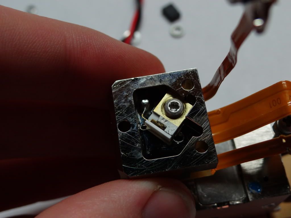
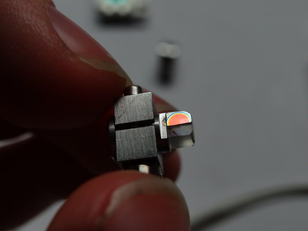
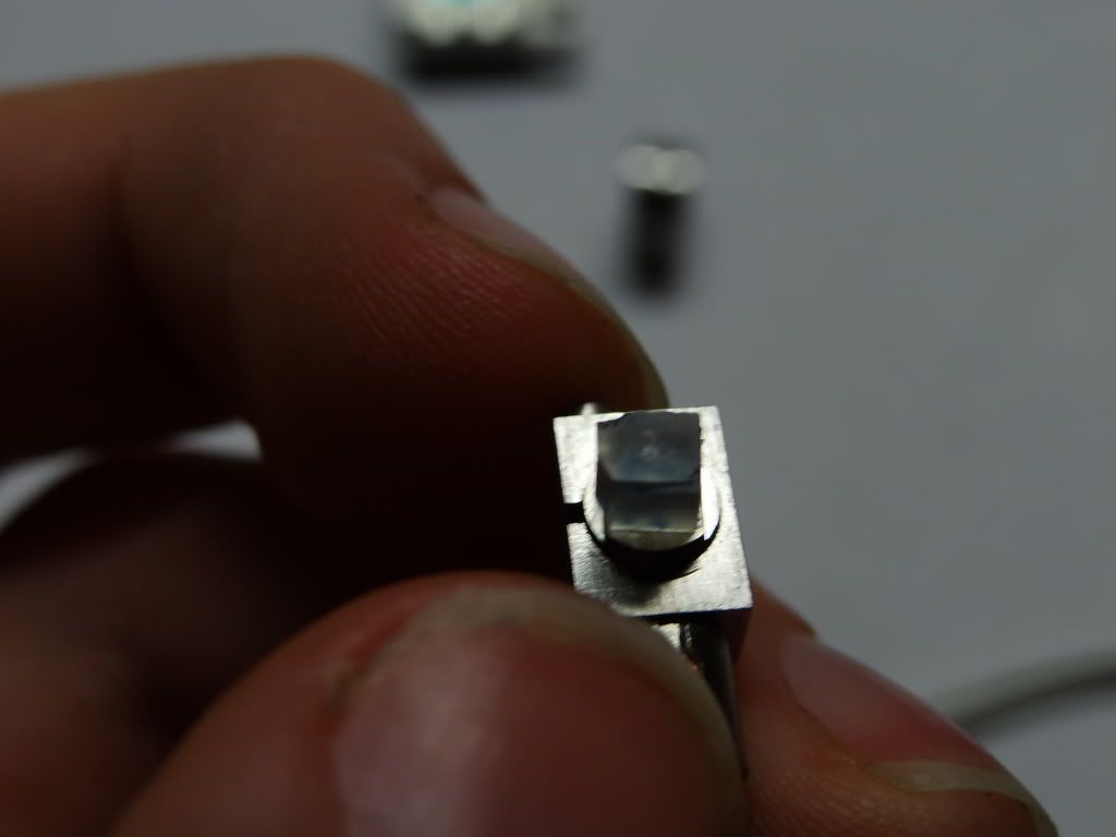
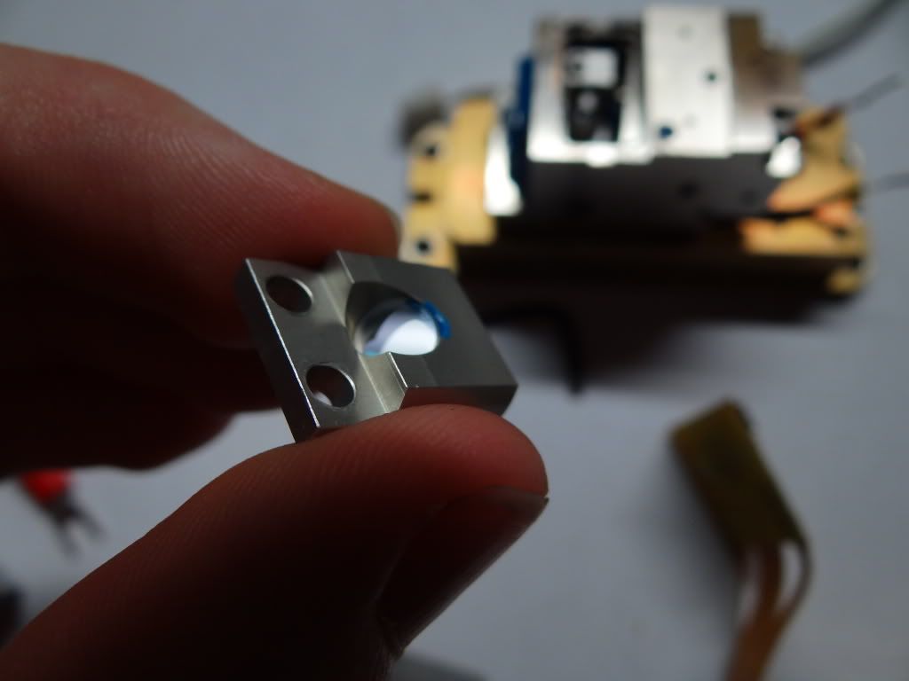
However when I got it home it did not work. so i sent it for Dr. Sam to look at and he sent me a functioning unit (laser B later on ) that emitted green light, But only as a splotch. so after opening it I noticed that the crystal was chipped. and upon putting it together I knocked the KTP of its mount ( In my defense it had obviously been repaired before As the door to the Optical cavity was taped shut. Also the crystal looked to have been re glued ) so I put it way until a few weeks ago.
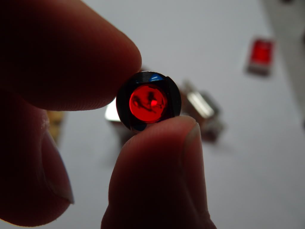
So long story short I told Sam I wanted to try to replace the KTP and he sent me another head.(laser C ) Also emitted a splotch.
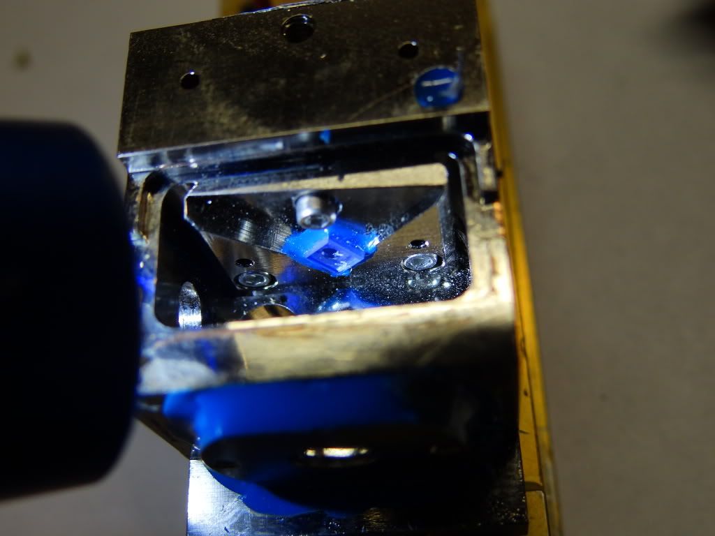
So after tinkering with the KTP mount trying to align the crystal for a wile I gave up.
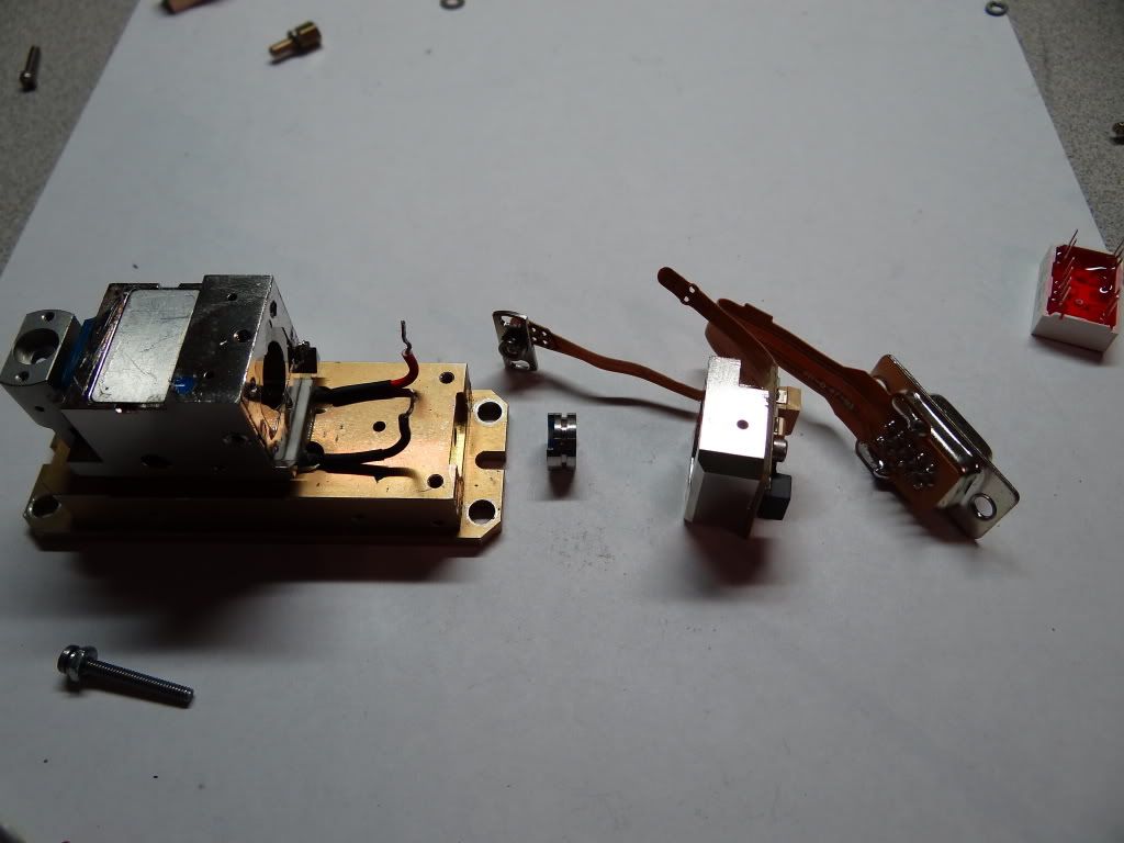
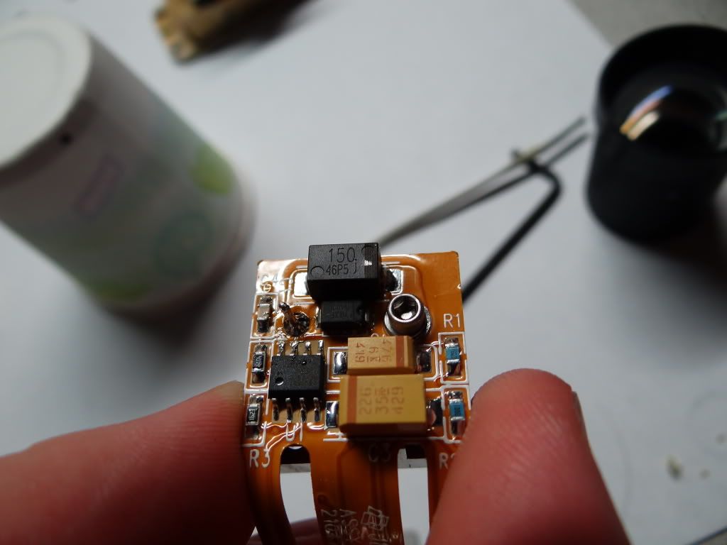
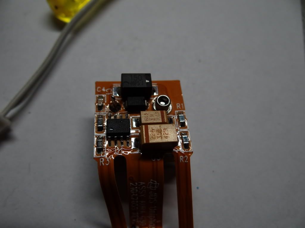
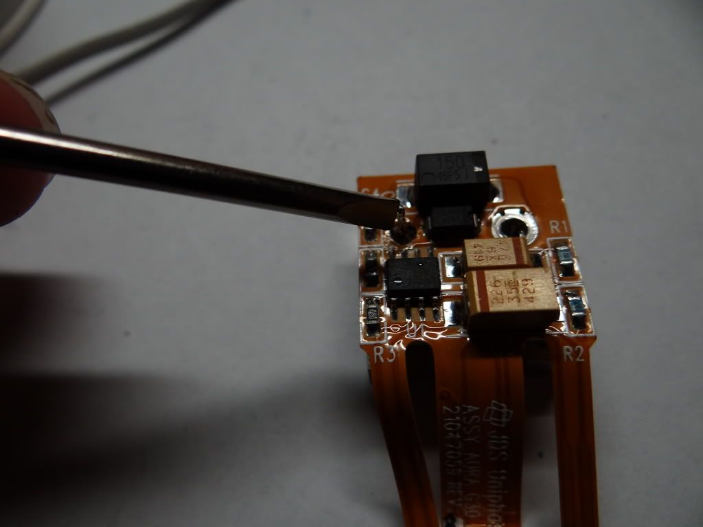
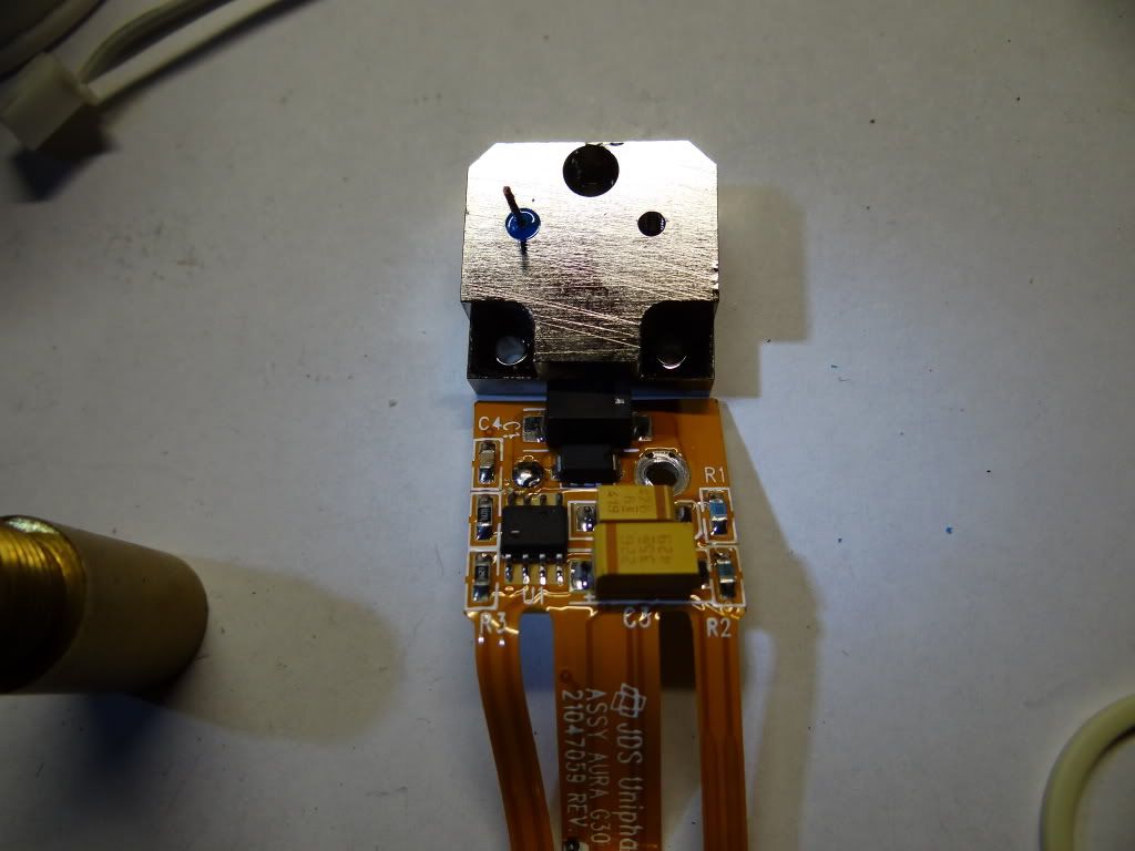
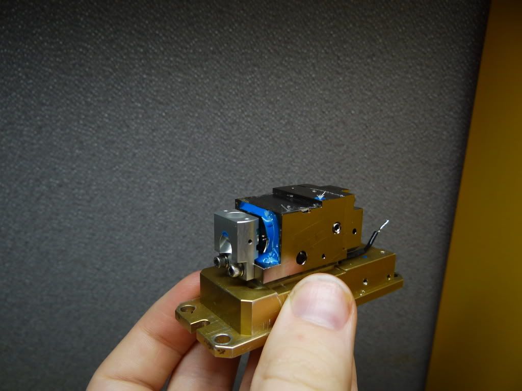
So I gutted laser B For its pump diode but after De-soldering the Robin cable and circuit board off it I ran into a bottleneck The 2 halves of the module were soldered together.
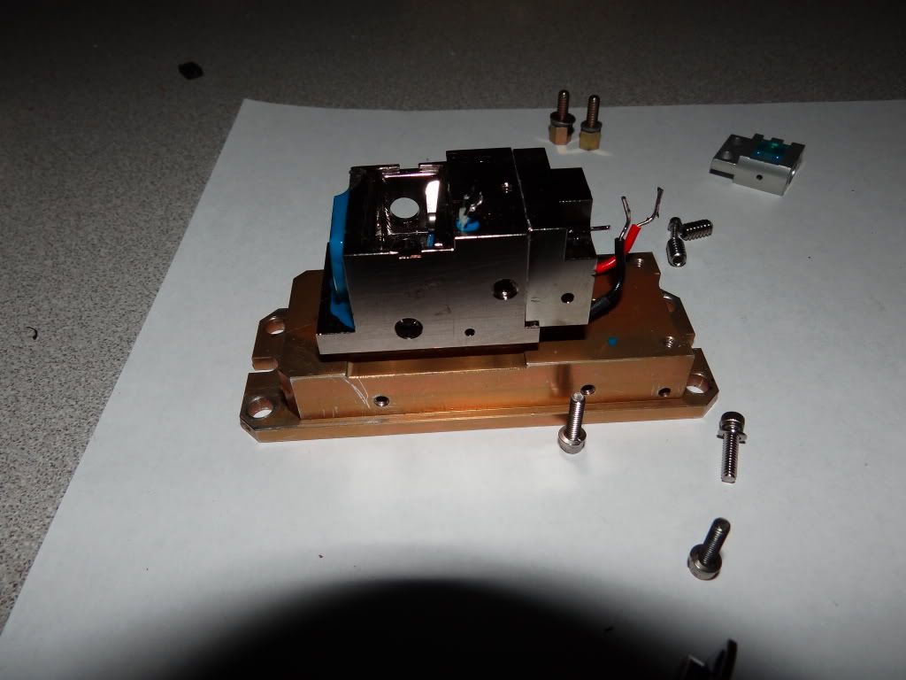
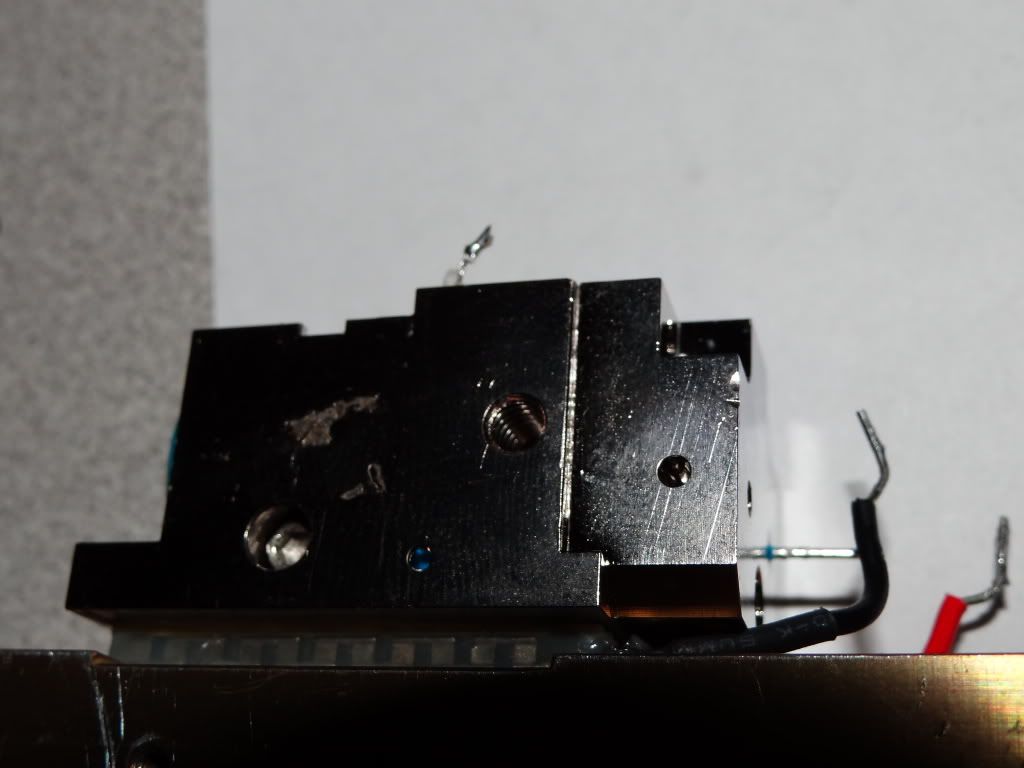
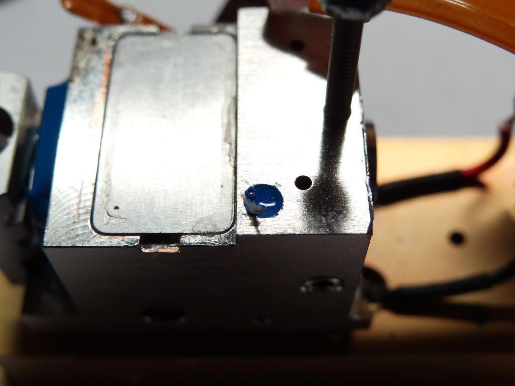
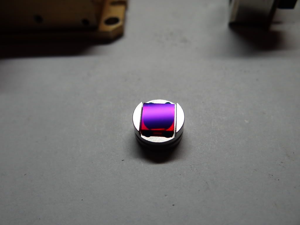
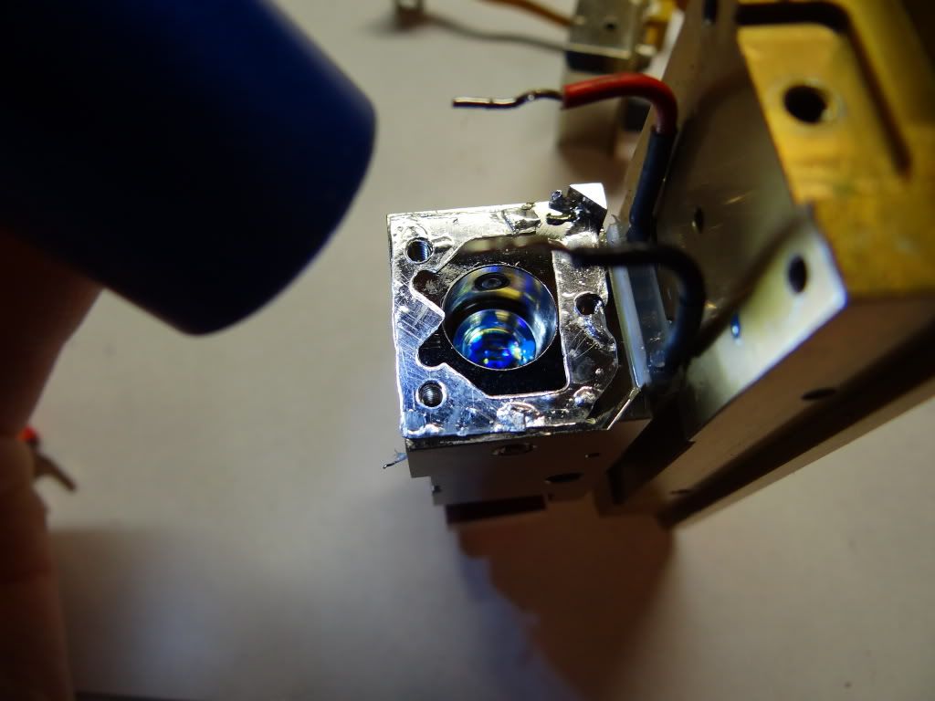
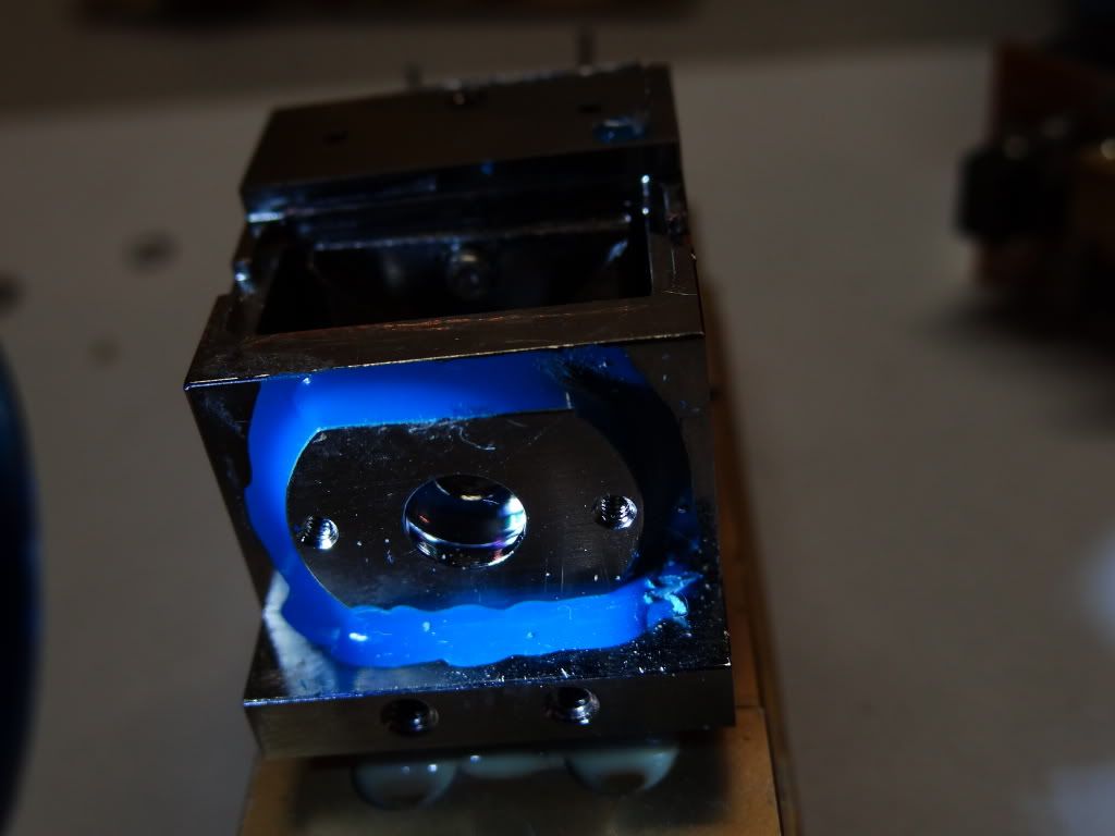
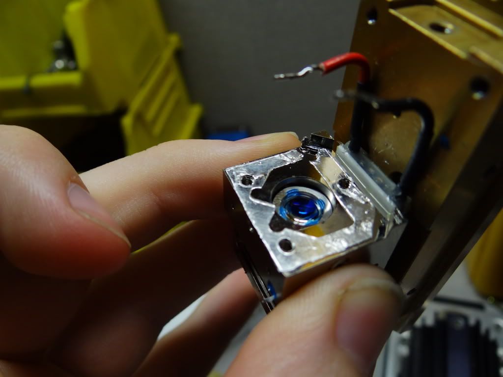
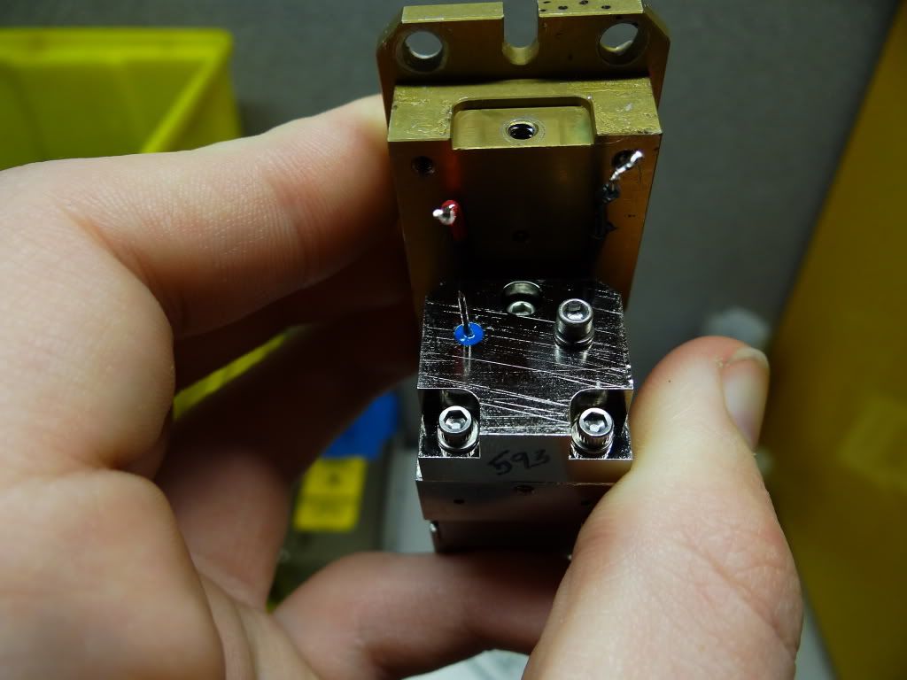
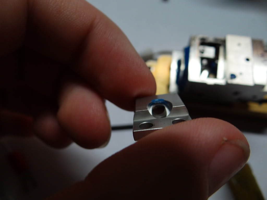
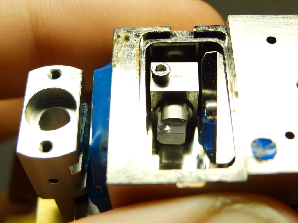
So just before I gave up I heard a raddled noise inside upon investigation I noticed a little cylinder inside through a screw hole.
Gee could it be more optics
so I turned to laser-head C to test.
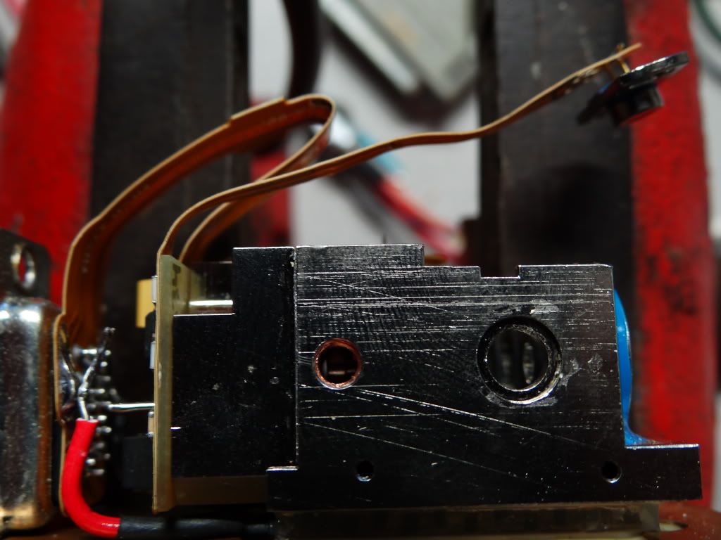
I turned on the head took out the setscrew and nudged the cylinder with a toothpick.
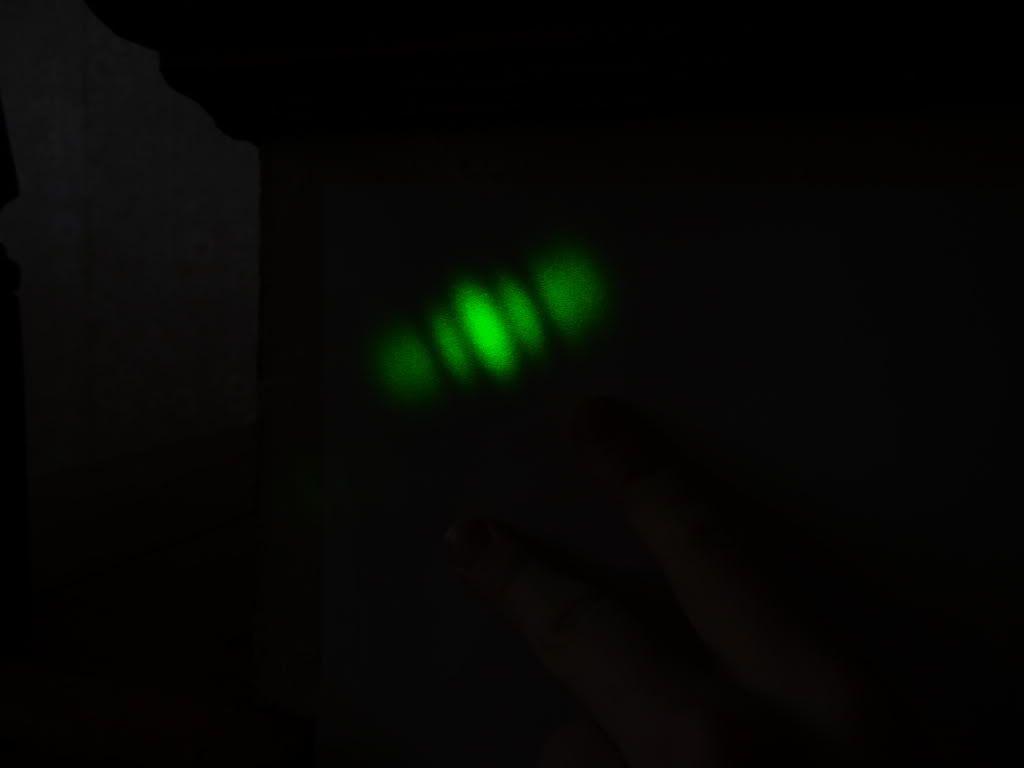
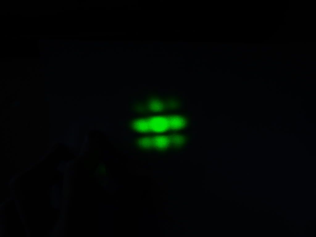
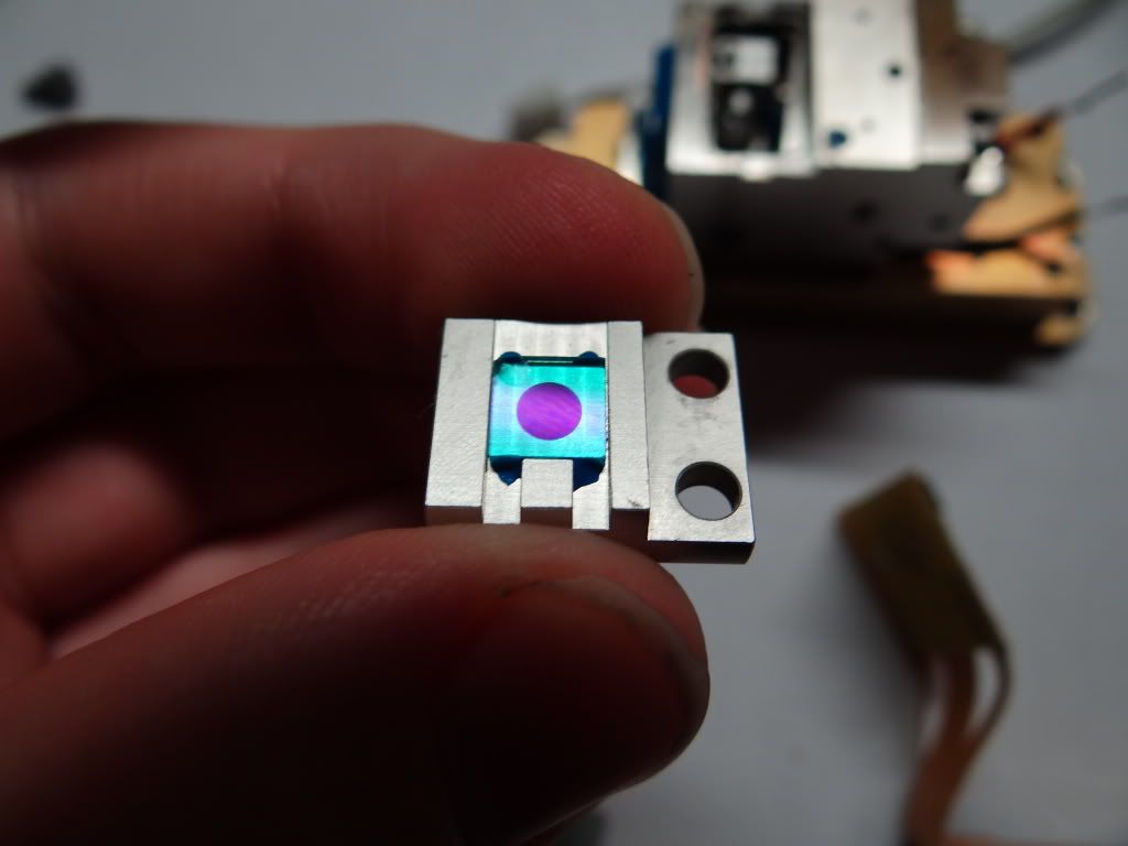
All of a sudden the Transverse mode changed.
So I messed with it for a wile each time going through weird transverse modes.
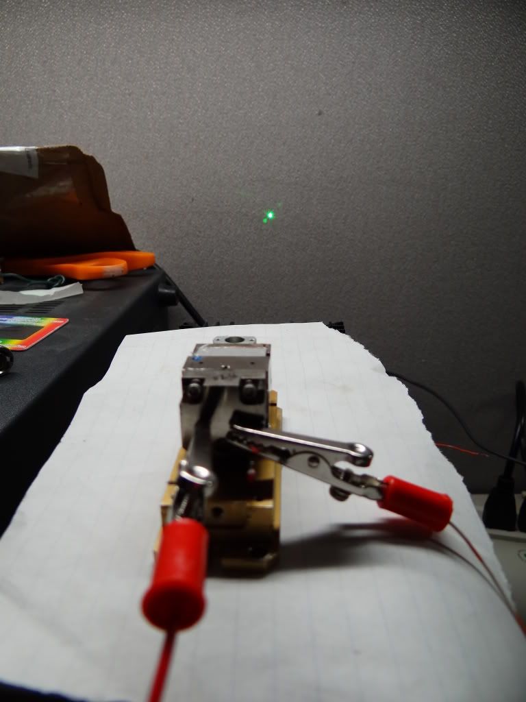
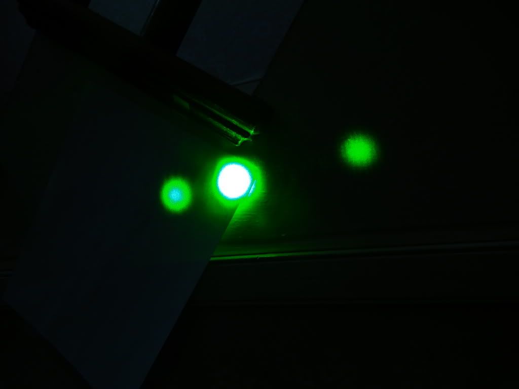
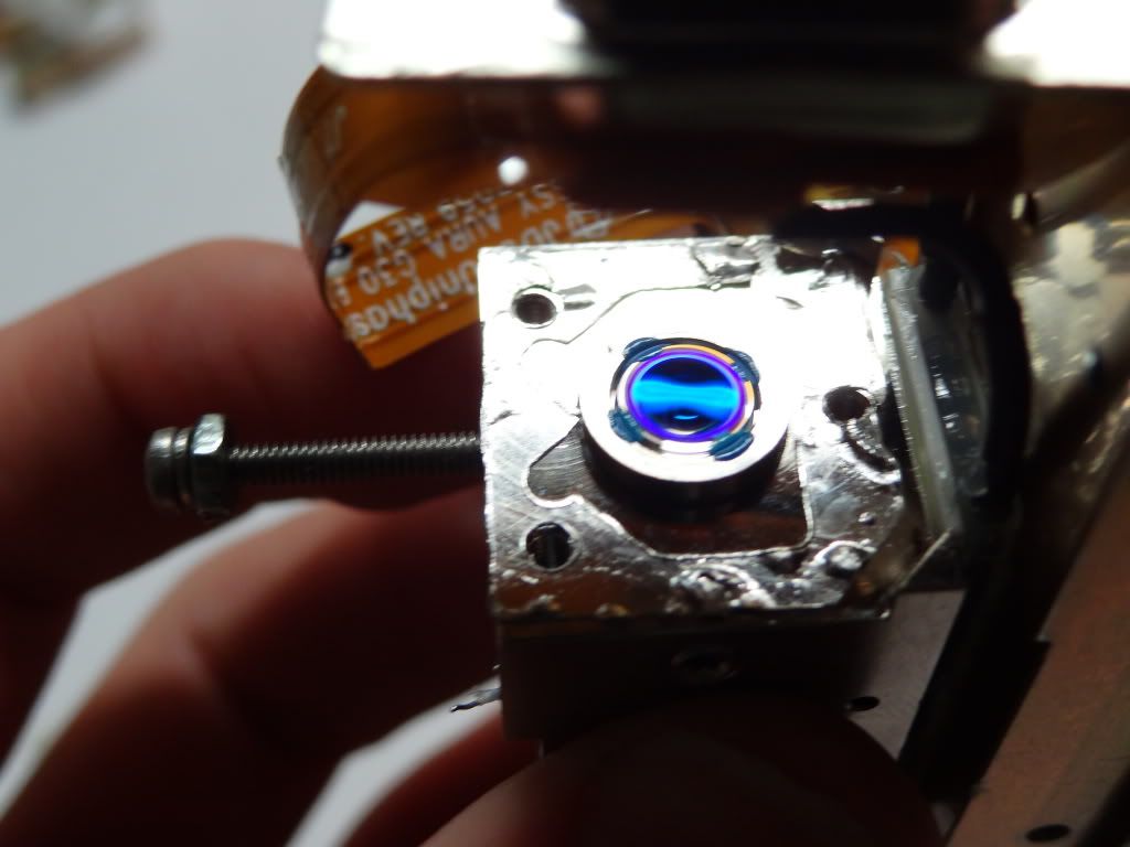
Then al of a sudden the power jumped and it stabilized at TEM00 or near it
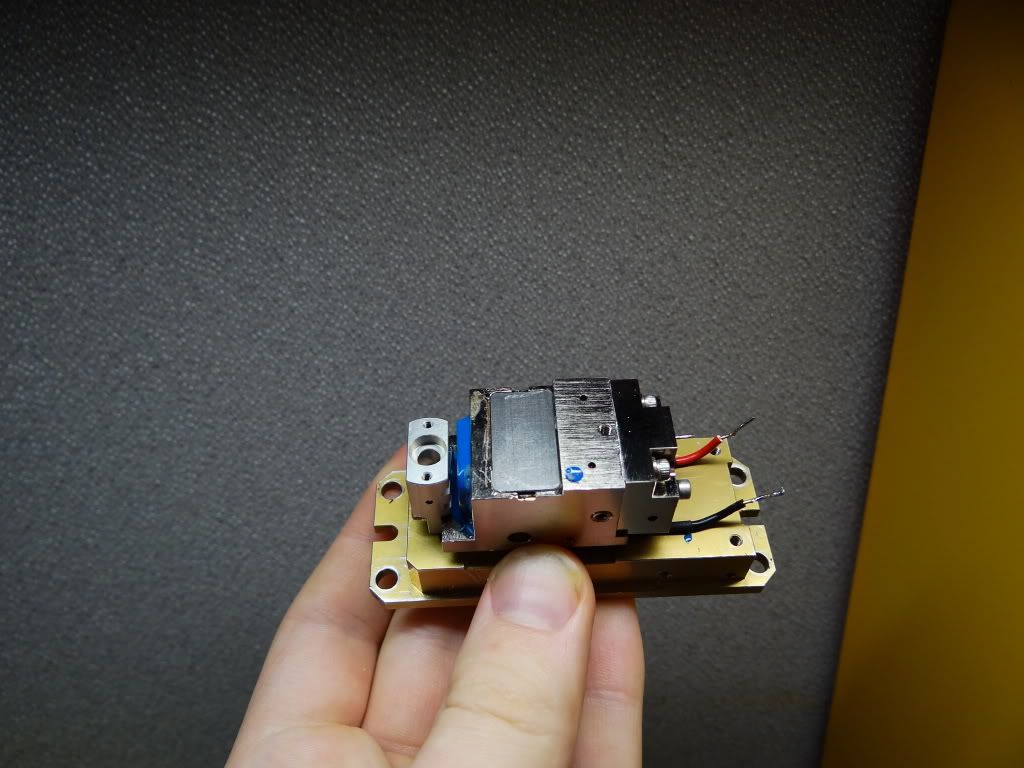
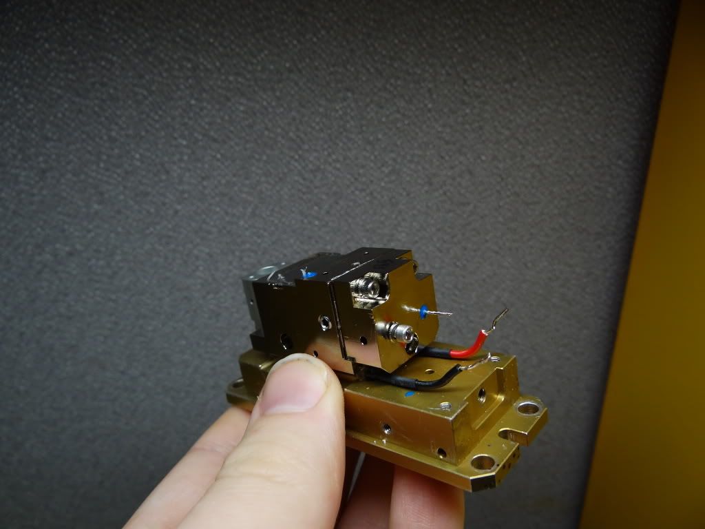
Long story short again I re-soldered laser-head B back together and did the same thing as with head C but lifted the KTP mount higher to avoid chip.
And it worked to just as good ad B and at least 50 mW
More to be updated in post 2
However when I got it home it did not work. so i sent it for Dr. Sam to look at and he sent me a functioning unit (laser B later on ) that emitted green light, But only as a splotch. so after opening it I noticed that the crystal was chipped. and upon putting it together I knocked the KTP of its mount ( In my defense it had obviously been repaired before As the door to the Optical cavity was taped shut. Also the crystal looked to have been re glued ) so I put it way until a few weeks ago.
So long story short I told Sam I wanted to try to replace the KTP and he sent me another head.(laser C ) Also emitted a splotch.
So after tinkering with the KTP mount trying to align the crystal for a wile I gave up.
So I gutted laser B For its pump diode but after De-soldering the Robin cable and circuit board off it I ran into a bottleneck The 2 halves of the module were soldered together.
So just before I gave up I heard a raddled noise inside upon investigation I noticed a little cylinder inside through a screw hole.
Gee could it be more optics
so I turned to laser-head C to test.
I turned on the head took out the setscrew and nudged the cylinder with a toothpick.
All of a sudden the Transverse mode changed.
So I messed with it for a wile each time going through weird transverse modes.
Then al of a sudden the power jumped and it stabilized at TEM00 or near it
Long story short again I re-soldered laser-head B back together and did the same thing as with head C but lifted the KTP mount higher to avoid chip.
And it worked to just as good ad B and at least 50 mW
More to be updated in post 2


")