Welcome to Laser Pointer Forums - discuss green laser pointers, blue laser pointers, and all types of lasers

LPF Donation via Stripe | LPF Donation - Other Methods

Links below open in new window

ArcticMyst Security by Avery

dx true 5

seoguy

0
Joined
Feb 9, 2009
Messages
263
Points
0
@milantheone:

Guys this is really great thread, but there is still missing some info how should be crystal (crystal holder) corectly aligned against the diode..

I am putting together some information for Greendream about this which I will post here when it is done, but like I told him, it's complicated!

i have already put off the crystal with holder from the diode..

Oops! :oops:

now i just need to know how to place it back.. i mean what should be the right position..

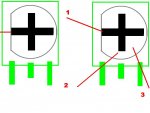
There isn't a standard "right position" - the crystals have to be aligned.

Are those red diagonal lines on the second picture and first graphic on the top half of your jpg how the crystals were lined-up before you took it apart? So that the crystals are rotated about 45 degrees from the chip in the laser? That is the same way my True 5 module crystals are lined-up, and it also has low output, so your crystals were likely mis-aligned as well!

Like I said, I am trying to put together some information on how to do this.

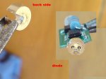
Hey, are those actual pictures of your module?

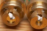
Well, as long as you have it all tore apart, can you do us all a favor, and get some larger pictures - of the back side of the crystals, and a close-up of the front of the laser diode?

That could allow us to find-out the specs on that diode they are using! :yh:

Thanks! :thanks:


seoguy

0
Joined
Feb 9, 2009
Messages
263
Points
0
Once I got my True 5 open, with a second unit to examine (I wasn't about to go prodding around my new 100mw module with a meter and accidentally kill it :eek:, but with a True 5, I was willing to take the risk ;)), I am happy to report that I have made great strides in my examination & analysis of the new DX driver! :yh:

As part of this, I have also been working-up a schematic for the device, and have that about 90% complete! :yh:

Unfortunately, some of the traces go under a couple components, making it impossible to follow them without destroying the device!

So if any of you have already "killed" one of these things, it would be extremely helpful to the cause and our understanding of these guys if you could do the following -

  • Unsolder the IC (IC1) from the board, and get a pic of the circuit traces under it. (This should be easy to do - just stick something under it to pry, and touch a soldering iron to the pins on one side of it and pry that side loose. Then either bend it out of the way, or grab it with a pliers, hit with other side with a soldering iron, and just pull it off the board)

  • Unsolder the pot, and get a pic of the circuit traces under it.

  • With the pot removed from the board, measure the resistance across it (between the two pins on the same side).

Once we have that information, I will be able to post a complete schematic on this guy, diagnose how this driver operates, and even be able to tell you how we can mod this board! :yh:

Thanks!
:thanks:
 
Joined
Jul 1, 2009
Messages
1,679
Points
0
wow that's a lot of reading, lol. I got this one open, it was at 254ma out of the box. This one was crazy hard to get out. I got to the point where I didn't care about saving the host, and I did try using a vice to get it off, but with now luck. After throwing it against the wall, and cursing up a storm. I fired up my dremel. That did the trick. But it got some dust on the lens which I am having a hard time getting off.
 
Joined
Feb 22, 2008
Messages
3,182
Points
48
modded two more yesterday one i took to 300 ma it went to 104 mw
the other i took to 275 ma and it peaks at 30 mw??? these are strange indeed
 
Joined
Jul 1, 2009
Messages
1,679
Points
0
modded two more yesterday one i took to 300 ma it went to 104 mw
the other i took to 275 ma and it peaks at 30 mw??? these are strange indeed

so you use the plier and leather method? and it doesn't damage the host? I've not been able to achieve that yet.
 
Joined
Aug 14, 2009
Messages
220
Points
0
vice grips are a must.. definitely better than crappy pliers.. lol.. :p
a big vice works well too.. but i don't have one of those.. bleh.

@seoguy
awesome info!! thanks alot
 
Joined
Dec 2, 2008
Messages
339
Points
18
yes, ok i will take some close up shots of the crystal and a diode, but i dont think they will be better from those already posted, as my camera is only my phone SONY ericsson k810i so my macro mode is really limited..
but i will take 30 shots and chose one which will be the best..
i will do that tommorw as there is 22.00 o clock right now..

and to your question:
Yes
those red diagonal lines on the second picture and first graphic on the top half of my jpg are how the crystals were lined-up before i took it apart.

anyway i was trying all day long to realign it but without success..

i really cant wait till there is some tutorial about the re-aligning process..


one more thing i would like to mention, those new batch of DX lasers comes with soooooo shitty batteries, that it is hard to describe, they are even not same in dimmensions (lenght and girth) as a standard AAA's.. when lasers from prewious batch comes with alkaline batteries those yellow and blue it was great. now those batteries are not even make a good touch with the spring and i need to use a spacer.. even then they last just a 3 minutes at max.. not wery good

also i have a litte bit different experience with potmoding those new's lasers.. when i turn the pot just a little bit it starts immediately mode-hop.. maybe just bad luck with those unit, but i dont know.. 3 of them with a same problem.. now i have another 6 on the way so i will keep you inform about them..
hopefully i will have a better luck..

thanx

Milan
 
Last edited:
Joined
Dec 2, 2008
Messages
339
Points
18
all right it is the mornimg actually and here comes some photos..

i think the crystal holder from the back is qite good, but i am unable to focus on the diode as you can see

i am so sorry, but those are the best 2 shoots form 45 i have taken

Milan
 

Attachments

  • lpf requested picture.JPG
    lpf requested picture.JPG
    39.2 KB · Views: 131

seoguy

0
Joined
Feb 9, 2009
Messages
263
Points
0
@john_lawson:

modded two more yesterday one i took to 300 ma it went to 104 mw the other i took to 275 ma and it peaks at 30 mw??? these are strange indeed

That is bizarre! What was the original current set to on those two? Did they both have the same type of crystal holder?

I don't know if you saw Greendream's EXCELLENT pictures on the previous page - but here is a Photoshop'd version of one, that clearly shows the two different crystal sets we have identified as being used on these guys so far -

23360d1253514353-dx-true-5-crystalsets.jpg


What happened on that one if you set the current any higher (like 299ma) - did the output go down below 30mw? That almost sounds like a bad diode, that is shifting too far from 808 when it gets warmed-up???


@bryce007:

wow that's a lot of reading, lol.

You should have tried writing it! :p

I had to finish-up on a client's project, that kept me away from replying on these threads for a few days, plus a lot of developments here on this end with these guys - I had a lot of catching-up to do! ;)

I got this one open, it was at 254ma out of the box.

254ma from the factory, just to get 5mw out? Did they put the crystals in backwards or something? :rolleyes:

With these recent reports, I'm beginning to wonder - when my new one comes in, am I going to have to hook it up to a car battery, just to get 5mw out? :thinking:

This one was crazy hard to get out.

Yea, these things are a real bitch to get apart with pliers! Now that I know the "secret", it will be interesting to see how hard the next one will be - but some way of holding the cap steady is definitely a must!

After throwing it against the wall, and cursing up a storm. I fired up my dremel. That did the trick. But it got some dust on the lens which I am having a hard time getting off.

I had always figured as a worst-case scenario, I could just hacksaw the end of the host off! LOL The only problem with this sort of approach (aside from possible vibrational damage to the module), is that it ruins the host! :cryyy:


@Shogoki:

@seoguy
awesome info!! thanks alot

Your welcome, Shogoki!

Once I get the driver photos I requested from anybody that killed one of these modules (post #130), I will be able to provide you with a more specific diagnosis on how to check / fix / improve yours! ;)


@milantheone:

i will take some close up shots of the crystal and a diode, but i dont think they will be better from those already posted, as my camera is only my phone...i am unable to focus on the diode as you can see

Yes, it is very hard to get good pics off a cell phone camera.

Do you have a friend with a digital camera that could take a picture of these for you?

one more thing i would like to mention, those new batch of DX lasers comes with soooooo shitty batteries, that it is hard to describe, they are even not same in dimmensions (lenght and girth) as a standard AAA's.. when lasers from prewious batch comes with alkaline batteries those yellow and blue it was great. now those batteries are not even make a good touch with the spring and i need to use a spacer.. even then they last just a 3 minutes at max.. not wery good

Yes, I thought they looked a little too small for AAA's also, but I thought it was just my imagination! I just compared one side-by-side with a regular AAA - the case IS smaller, but they made the plus terminal longer to compensate.

But when I saw they were not even alkaline, I immediately replaced them with alkaline ones. You need good alkaline AAA's to run these guys, especially if you pot mod them for higher power! (And for the higher-power DX modules, even brand-new alkaline's won't work - you need to use at least AA's to get those to full power! ;))

also i have a litte bit different experience with potmoding those new's lasers.. when i turn the pot just a little bit it starts immediately mode-hop.. maybe just bad luck with those unit, but i dont know.. 3 of them with a same problem..

That's odd. I know the pots on these things are REAL sensitive. That is because they are using the same driver on the higher-power modules, so it has a big range. For example, my 100mw module, is set from the factory at 530ma, and the pot is not even turned up halfway! :rolleyes:

Still, they shouldn't mode-hop.

How much current were these drivers using originally from the factory? And how much did you set them to when they started to mode-hop?

Also, were the crystal holders in all 3 the same? (See the pic above).
 

Attachments

  • CrystalSets.jpg
    CrystalSets.jpg
    99.3 KB · Views: 298
Last edited:
Joined
Dec 2, 2008
Messages
339
Points
18
i am so sorry but ATM i dont have anyone to take a better pictures..

of course i am not using those batteries which comes with laser now, ther are totaly not suitable. and thats what i want to mention, it is very bad point for DX now.. prewious batch was better IMO..

also as i mentioned couple of pages ago i am unable to measure current drawing..
i was pointed to replace a battery in my mutimeter, but it didnot heplp.. my multimeter is digital so i dont need to set a scale though..

unfortunately i put them immediately together after i was trying to pot mod them, so i really cant say how crystal holders in each one looked like..


i am attaching a picture how i used to pot prewious batch of my lasers..

lets imagine one more time that first picture red line is showing how potentiometer is currently turned..

number 1 position line on the right side of the picture is how my prewious batch of lasers used to be turned when i opened them up..
number 2 position is how i used to turn the pot to get perfect results..

now with new batch i can also turn pot to the position 3 to get same increasing in power with comparision to the prewious batch..
i am always talking about counter clokwise turn..
 

Attachments

  • bez_názvu.JPG
    bez_názvu.JPG
    38.5 KB · Views: 100
Last edited:
Joined
Jul 1, 2009
Messages
1,679
Points
0
it was 254ma out of box, but it definitely was over 5mw. I don't have my meter yet, but I would say it was about 20-25mw out of box.
 
Joined
Feb 22, 2008
Messages
3,182
Points
48
@ seoguy i havent taken the lenses apart on any yet
i just give it a small ccw turn

hey this is the first time i had a thread go this long
I feel important now
 
Joined
Jul 1, 2009
Messages
1,679
Points
0
@ seoguy i havent taken the lenses apart on any yet
i just give it a small ccw turn

hey this is the first time i had a thread go this long
I feel important now

you give it a small turn? You can turn your lenses? I sure can't. I've even soaked one in alcohol trying to dissolve the glue, but with no luck.


Top