Welcome to Laser Pointer Forums - discuss green laser pointers, blue laser pointers, and all types of lasers

LPF Donation via Stripe | LPF Donation - Other Methods

Links below open in new window

ArcticMyst Security by Avery

dx true 5

Joined
Jul 27, 2009
Messages
120
Points
0
My experience with pots is limited, but I've only come across pots that stop once they reach their limit.

I wonder if you could bypass the pot to check, but I suspect you'd need another pot or resistor or you might risk frying the pump diode or even another component in the driver?


seoguy

0
Joined
Feb 9, 2009
Messages
263
Points
0
@Greendream:

How are these?

Awesome! :yh:

+Rep! :gj:

Excellent macro shots - what kind of camera are you using?

I was hoping the crystals in yours would be identical to my new 100mw module, but yours looks slightly different.

At first I thought the crystals in that looked smaller than mine. But after examining mine again, it appears the crystals may be the same, but the crystal HOLDER is "taller" on yours.

Different construction/supplier for the crystal module, perhaps?

Edit to add - I measured the crystal to be 2mm long, perhaps a fraction over.

Same here - I estimated mine to be a tad over 2mm in length. Is yours about 1mm square on the end?

Is it me or is that obviously misaligned?

Hard to tell, but something does look a little off-kilter!

Your crystals are also lined-up 90 degrees offset from mine. In mine, the "notch" lines-up with the horizontal axis of the diode die.

On yours, the notch is located vertical, directly ABOVE the diode die.

It seems that way...

Yeah, that's exactly what I'm thinkin too.

I beginning to wonder if there is another cause as well (see below).

Yes... I had the laser within about 1 inch of the sensor, so I think that would get almost all of the IR?

Likely, if the sensor was large enough. What kind of meter are you using?

Originally Posted by seoguy
Is hard to tell from angle of photo - if you look dead-on at top of that tiny crystal, is it perfect square shape on end?

Yes, near enough.

Near enough, or a perfect square? The reason I ask is that there are some crystals that are slightly rectangular on the end, that could make a difference.

Not exactly sure what an open can (or closed for that matter) looks like TBH, but hopefully you can tell from the pix?

An open-case diode does not have a case around it, they tend to be high-power diodes, like this -

23292d1252920031-dx-true-5-opencan1.jpg


The other ones are completely enclosed by a metal case, with a little window at the top for the laser beam to exit, like this -

23293d1252920047-dx-true-5-closedcan1.jpg


It is apparent from your pics that this is an open-case diode, as you can see the diode die and some wires attaching to it! See -

23294d1252920068-dx-true-5-true5opencan1.jpg


All 3 of the wires/pins are straight.

So when you look at those two where they go into the diode, the pins are exactly the same width apart as on the board, they don't bend in or out a bit to fit?

If so, it sounds like that is a 5.6mm diode then. My 100mw has a 9mm diode, and those two pins have to bend in slightly in order to match the solder points on that driver board.

The next one came apart much more easily... about 2 minutes vs 10 minutes working it for the other, so that would explain why some are finding it easier than others.

Ah ha!

344/61 (probably didn't give it time to climb)

In a green laser, this can be caused by over-heating the diode. The vandate crystal has a VERY narrow pumping bandwidth at ~808nm. If the IR laser diode gets too hot, it's wavelength can shift out of the optimum pumping range, causing a reduction in green output.


There is something I am beginning to suspect here...

The True 5's that Bob_Boyce reported being able to mod to upwards of 70mw or more of green at <300ma, they all came set from the factory set at ~170ma or so.

Mine was set at 170ma, and is a bear to try to take apart. You also noticed that the one that was much harder for you was also the 176ma unit.

I have heard several reports now of units that come from the factory set at >= 200ma, and in every case, their performance was lacking, they could not be modded nearly as high, and you had to pump at LOT more current into them to get there!

The crystal holder in the one you took a pic of (a 200ma one), also appeared a bit different than my 100mw (although this could also be a difference between the low & high-power modules).

I am beginning to wonder if these 200ma guys are a newer, more sucky design - perhaps using less efficient crystals or laser diode?

Take a REAL close look at your 62mw mod pen, and compare it to the other two. Compare the crystals - is the crystal holder not quite as tall as the others? Does the crystal assembly look any different? What about the diode - both the back from the outside, and what you can see through the hole - does it appear identical? Is the driver exactly the same?

Can you notice any difference between that higher-power one and the other two?
 

Attachments

  • OpenCan1.jpg
    OpenCan1.jpg
    88.5 KB · Views: 380
  • ClosedCan1.jpg
    ClosedCan1.jpg
    56.4 KB · Views: 389
  • True5OpenCan1.jpg
    True5OpenCan1.jpg
    83.7 KB · Views: 389
Last edited:

seoguy

0
Joined
Feb 9, 2009
Messages
263
Points
0
@bryce007:

You're making a chart? Mine was 173ma out of box (using the batteries it came with), I set mine to 290ma using a 16340.

OK, added yours! :yh:

BTW, you might want to run that 16340 through a diode, as I think that battery may deliver too much voltage, overloading the driver and causing it to fall out of regulation. In addition to wasting battery power over-heating components, your current to the diode will vary, depending on how full your battery is! :rolleyes:


@Shogoki:

but is there a reason or explanation i can't get the current reading any higher?

You may have damaged the driver from over-voltage.:cryyy: Even with a poor diode, that driver should be able to push it well past that point!

It's also possible those 200ma units may be designed a bit differently, see my post to Greendream above about that.

Also, what meter range are you using to measure it?

however as i said.. i can turn it round and round without a stop (is that normal for a pot? i usually feel a stop or something on other pots i've dealt with..)

Yes, there are cheap pots like that - they just don't have any stops, to keep them from turning 360 degrees.

IMHO that kind of pot is NOT good to use for a laser driver, however! The wiper can "fall off" one end of the resistive track before climbing back onto the other end, causing voltage spikes and an intermittent connection.

haven't had much time to take the remaining 3 apart yet.. just kinda putting them into a "storage" state for now while i continue to play around with the one i tore apart.

Shogoki, you might want to check their current at least, so you can see if you have any 170ma units - you should be able to do that without taking them apart. If you have any of the 170ma ones, you may want to take that one apart, just to see how it performs compared to your 200ma one! :yh:


@milantheone:

well i am totaly unable to take any current readings from my green lasers..

when i am measuring my blu-ray which is set at 125ma my multimeter show me around 140ma which is i think okay, but i am unable to take measurement on my green lasers..

Why?

What meter range are you using to measure it?

I recently tried to measure the current on a 10mw green pen, and my meter readings went all wonky. It turned-out the cause was that the pen was drawing more current than I expected (~230ma), and it was beyond the range I had the meter set to!

Many cheap meters' normal ma range max's-out too low to measure many green DPSS lasers, due to the higher currents these run at. Try setting the meter to the max Amp mode (10A or something), change the plus lead to plug into the other hole made just for that, and see if it works now! ;)
 
Joined
Jul 27, 2009
Messages
120
Points
0
@Greendream:

Awesome! :yh:

+Rep! :gj:

Excellent macro shots - what kind of camera are you using?

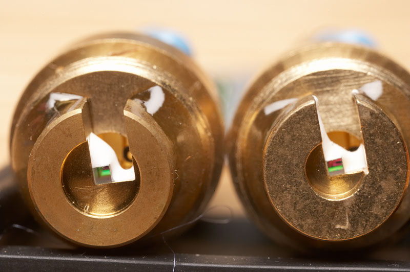
Thanks seoguy. The first two batches of shots were taken with a Ricoh G3 3MP point and shoot (it has a pretty sweet macro mode). The last couple were all taken with a Canon 1Ds mkII/MPE 65mm macro lens using a tripod and macro-rails, since positioning was more critical, as well as offering more magnification. The first shot in the last batch was at about 2.5x magnification, the other two were crops also at 2.5x.

I was hoping the crystals in yours would be identical to my new 100mw module, but yours looks slightly different.

At first I thought the crystals in that looked smaller than mine. But after examining mine again, it appears the crystals may be the same, but the crystal HOLDER is "taller" on yours.

Different construction/supplier for the crystal module, perhaps?

Yes... after comparing mine, there are differences in the crystals and "crystal holder" part of the module. See below...

Same here - I estimated mine to be a tad over 2mm in length. Is yours about 1mm square on the end?

Yes, I'm pretty sure it was not far off, but I've put the pen together again now so I can't check.

Hard to tell, but something does look a little off-kilter!

To my eye, and if I'm understanding module construction, that pump diode looks at least 25 degrees off axis. They must literally slap these modules together, and not care if something is off... which is great cos it means we are getting (potentially) high power modules for peanuts!

Now all we need is someone to explain how to re-align the components ;)


Your crystals are also lined-up 90 degrees offset from mine. In mine, the "notch" lines-up with the horizontal axis of the diode die.

On yours, the notch is located vertical, directly ABOVE the diode die.

Interesting, but would it make any difference? Since the crystal is square, and more or less centered in the holder, a 90 degree rotation should not affect the function as far as I can see.

It does point to the supply of components that make up the module changing. That would suggest that the factory where these modules were assembled is not the same place as where the parts were manufactured IMHO.


Likely, if the sensor was large enough. What kind of meter are you using?

Using a laserbee, which is not the biggest sensor around... I'll repeat some tests with one of the pens and see if moving it a bit closer makes much of a difference.


Near enough, or a perfect square? The reason I ask is that there are some crystals that are slightly rectangular on the end, that could make a difference.
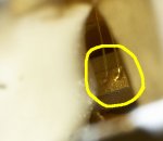
Closer to square than rectangle I'd say. See below...


An open-case diode does not have a case around it, they tend to be high-power diodes, like this -

23292d1252920031-dx-true-5-opencan1.jpg


The other ones are completely enclosed by a metal case, with a little window at the top for the laser beam to exit, like this -

23293d1252920047-dx-true-5-closedcan1.jpg


It is apparent from your pics that this is an open-case diode, as you can see the diode die and some wires attaching to it! See -

23294d1252920068-dx-true-5-true5opencan1.jpg

Thanks for explaining that. I agree, it looks like an open can.

So when you look at those two where they go into the diode, the pins are exactly the same width apart as on the board, they don't bend in or out a bit to fit?

If so, it sounds like that is a 5.6mm diode then. My 100mw has a 9mm diode, and those two pins have to bend in slightly in order to match the solder points on that driver board.

They are not perfectly parallel to each other if that's what you mean, but not far off, the non insulated pin seems to be perhaps 5 degrees or less, bent more outwards towards the driver. The other two pins I would say are parallel to each other.


In a green laser, this can be caused by over-heating the diode. The vandate crystal has a VERY narrow pumping bandwidth at ~808nm. If the IR laser diode gets too hot, it's wavelength can shift out of the optimum pumping range, causing a reduction in green output.

Yeah, that may have been a cause... I wasn't too critical about letting the module cool down between tests that time.


There is something I am beginning to suspect here...

The True 5's that Bob_Boyce reported being able to mod to upwards of 70mw or more of green at <300ma, they all came set from the factory set at ~170ma or so.

Mine was set at 170ma, and is a bear to try to take apart. You also noticed that the one that was much harder for you was also the 176ma unit.

I have heard several reports now of units that come from the factory set at >= 200ma, and in every case, their performance was lacking, they could not be modded nearly as high, and you had to pump at LOT more current into them to get there!

The crystal holder in the one you took a pic of (a 200ma one), also appeared a bit different than my 100mw (although this could also be a difference between the low & high-power modules).

I am beginning to wonder if these 200ma guys are a newer, more sucky design - perhaps using less efficient crystals or laser diode?

I think it's just the misaligned pump diodes that are causing the vast differences in performances, although differences in some of the crystals also must be contributing...


Take a REAL close look at your 62mw mod pen, and compare it to the other two. Compare the crystals - is the crystal holder not quite as tall as the others? Does the crystal assembly look any different? What about the diode - both the back from the outside, and what you can see through the hole - does it appear identical? Is the driver exactly the same?

Can you notice any difference between that higher-power one and the other two?

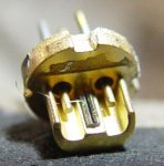
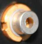
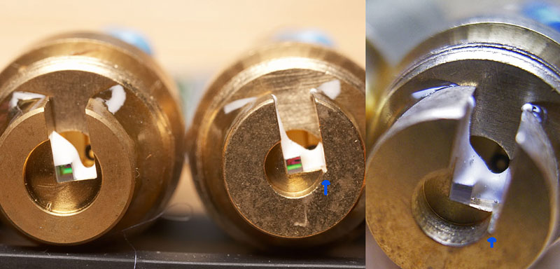
All 3 pens have exactly the same drivers. I'm sure of that. I got some more pics - pen 3 on the left and pen 1 on the right:
3920725522_db49a8a3c2_o.jpg


Face on:
3920725528_0834a64fe9_o.jpg


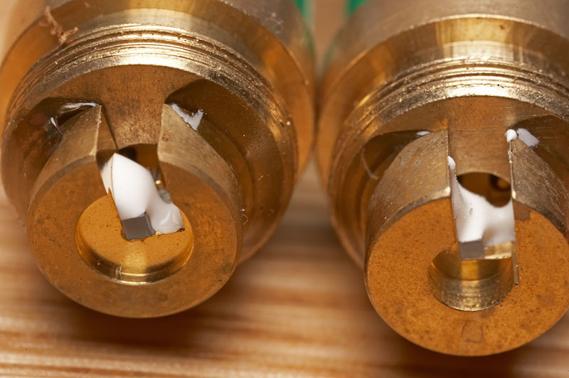
As you can see, pen 1 is a different crystal holder/crystal... the same as pen 2 (on the right in the pic below)

3920372535_49f8691ecd_o.jpg


3920725532_cac51f2f50_o.jpg


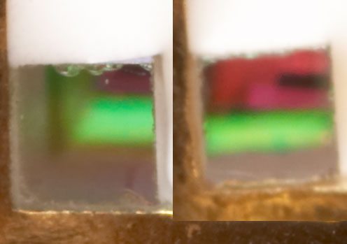
I've enlarged and moved the crystal faces from the previous shot so that they are next to each other for a rough comparison of area.

Although pen 1 is slightly further back (out of focus), at these magnifications depth of focus is razor thin, and a few mm forward or back will be the difference between sharp and in focus and blurry/out of focus, but the apparent decrease in size will be negligible.

I would say that's at least a 20% increase in crystal surface area by the looks of it!

Edit:

PS. I'll get a few more shots looking into the PD housing and post them here in the next few days. If there are any more requests for different angles/parts, post them up and I'll try to get them as well while these two units are still in bits.
 
Last edited:
Joined
Apr 2, 2009
Messages
10,662
Points
113
To GreenD-your photos are the best I've ever seen-+rep to you sir! To everbody else thanks for so much great info on these!!! FYI I Ordered three of them 8/29 they arr. in S/ Texas today- all three have the big resistor YAAHOO.Wish I had oredere 5) lack LPM but all look about the same and dang bright - so I am guessing Customs and the FDA dont have me on thier 'list' after all(they took 17 5mWgreenies from a shipment of mine in july 2007 for being overspec. ----------Now to get them open unharmed!! thanks all!! m<(*U*)>m
 
Joined
Jul 27, 2009
Messages
120
Points
0
Thanks hakza :) Nice to hear you got a few good ones. Good luck getting them open! Take your time and increase the amount of muscle you use gradually at first. Once you see that first hair-line gap, you're half way there.
 
Joined
Aug 14, 2009
Messages
220
Points
0
@Shogoki:


You may have damaged the driver from over-voltage.:cryyy: Even with a poor diode, that driver should be able to push it well past that point!

It's also possible those 200ma units may be designed a bit differently, see my post to Greendream above about that.

Also, what meter range are you using to measure it?


Yes, there are cheap pots like that - they just don't have any stops, to keep them from turning 360 degrees.

IMHO that kind of pot is NOT good to use for a laser driver, however! The wiper can "fall off" one end of the resistive track before climbing back onto the other end, causing voltage spikes and an intermittent connection.


Shogoki, you might want to check their current at least, so you can see if you have any 170ma units - you should be able to do that without taking them apart. If you have any of the 170ma ones, you may want to take that one apart, just to see how it performs compared to your 200ma one! :yh:


@milantheone:


What meter range are you using to measure it?

I recently tried to measure the current on a 10mw green pen, and my meter readings went all wonky. It turned-out the cause was that the pen was drawing more current than I expected (~230ma), and it was beyond the range I had the meter set to!

Many cheap meters' normal ma range max's-out too low to measure many green DPSS lasers, due to the higher currents these run at. Try setting the meter to the max Amp mode (10A or something), change the plus lead to plug into the other hole made just for that, and see if it works now! ;)

i was using a Fluke DMM.. can't remember the exact model.. 179 maybe? it was set on the mA range... so range should have not been an issue as in that setting it should read up to 400mA fine.

will most certainly need to check out the other ones i got at another time.
 
Joined
Aug 14, 2009
Messages
220
Points
0
well when i test it with new alkaline batteries.. without the bottom screwed on.. seems my current has now jumped to the 370mA range.. :wtf:

ehh.. figures..

but as long as i'm using the ampmeter and measuring current.. seems the brightness of the laser holds up very well..
however, once i install the batteries in and close the laser up... it has an initial bright dot at startup.. and then fades away to a weak dot..

suspect part of it is due to the poor contact the positive side of the battery has with the case.. then perhaps other reasons too..

further comments? ideas?
 
Joined
Jul 1, 2009
Messages
1,679
Points
0
your current jumped up because your input voltage is higher. A "driver" is supposed to supply the diode with a constant current independent of input voltage. I'm not sure if we call this circuit a driver on these DX modules, because the current to the diode is dependent on input voltage. Anyway, you need to set the current using your desired batteries at full charge to avoid killing the diode by jumping up to 370ma.
 
Joined
Aug 14, 2009
Messages
220
Points
0
yea... definitely not much of a "driver"..

looks like after a few shots, the batteries have lost enough charge to be about 3.04 volts (measured across the batteries with DMM)

which holds the current at about 350mA.. and the diode doesn't do that weird fading away thing after startup anymore... and it holds a pretty damn bright dot.. (wish i could measure it.. oh well..)

anyway.. thinking of leaving it as is.. and doing so, i'm giving it a good duty cycle.

it's only $10.50 for this thing anyway.. if i kill it, at least it'll go out in semi-glory.. that and a few people wanted the crystal from it if i kill it anyway.. so it won't end up going in the trash anyway. :p

well.. i already have friends wanting me to order a few more for themselves.. and will probably pick up a few more for myself sometime in the future.. just hope DX or the manufacturer don't change what they've been doing.. (unless they start putting in like turned down 100mW modules in them since they can't get rid of them anymore.. or something.. lol)

eh. probably will get me a PGL or something from CNI eventually from Glenn's GB or something..

in the meantime. see you guys using lasers responsibly :)
 
Joined
Jul 1, 2009
Messages
1,679
Points
0
yea proto wouldn't mind if you killed one, lol. Just crank it up to 400ma, lol.
 
Joined
Aug 14, 2009
Messages
220
Points
0
haha.. well.. when i was tweaking it with the PSU, i cranked the pot pretty much to the max current it could give me..

so... i think it's pretty much at its limit now.. the only way i can think to probably kill it.. would probably be to somehow get enough voltage pumping through to have the "driver" exceed the current enough to kill the diode completely...
( as i've probably partially damaged it from all this testing.. though it certainly still shines bright.. and it still works.. :p )

dunno... haha.. still would love to buy me a bunch more to just have..
anyone try the supposed 405nm 5mW one they got yet?
 
Joined
Jul 1, 2009
Messages
1,679
Points
0
I got two more of these in today, and I've been trying to get one apart for like 3 hours off and on today. This thing will not budge. I don't know how you guys get these off with just pliers, with no marks on them and then put them back together. I have to totally destroy these pens to get them apart.
 
Joined
Dec 2, 2008
Messages
339
Points
18
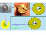
Guys this is really great thread, but there is still missing some info how should be crystal (crystal holder) corectly aligned against the diode..

my laser definitely require aligning and i have already put off the crystal with holder from the diode..

now i just need to know how to place it back.. i mean what should be the right position..

i draw a picture in a paint soft which show you how my crystal in holder was placed on the diode.. it is marked with a red line..

now i would like someone to edit my picture and mark with a red line some possible right possition of the crystal holder (crystal)..

is there anyone who know the right possition?

cheers in advance..

Milan
 

Attachments

  • crystal align3.JPG
    crystal align3.JPG
    55.4 KB · Views: 149
Last edited:

seoguy

0
Joined
Feb 9, 2009
Messages
263
Points
0
@Greendream:

Thanks seoguy. The first two batches of shots were taken with a Ricoh G3 3MP point and shoot (it has a pretty sweet macro mode). The last couple were all taken with a Canon 1Ds mkII/MPE 65mm macro lens using a tripod and macro-rails, since positioning was more critical, as well as offering more magnification. The first shot in the last batch was at about 2.5x magnification, the other two were crops also at 2.5x.

I used to be heavy into photography, and have been looking for a nice point-and-shoot with full manual mode ability, and excellent macro capability a must. I was thinking about the Canon A590IS, until they got a good review in Consumer Reports, and price/availability went nuts as a result! Thinking about perhaps one of the older A series? Any suggestions?

To my eye, and if I'm understanding module construction, that pump diode looks at least 25 degrees off axis.

Rotated, or tilted? These lower-power modules, the diodes appear to just be pressed-in to a hole on the back. Look at the back side of the module closely - does it appear that the diode was pressed-in at an odd angle?

They must literally slap these modules together, and not care if something is off...

That's my impression too! Something I heard in the module thread, and discovered the same thing on my True 5 module as well(!) - When I take either the top or center section separately, and shake it -
it rattles! :wtf:

which is great cos it means we are getting (potentially) high power modules for peanuts!

That's my hope, at least! :yh:

Now all we need is someone to explain how to re-align the components

I'm working-up something on that for you - but it's very complicated!

Interesting, but would it make any difference? Since the crystal is square, and more or less centered in the holder, a 90 degree rotation should not affect the function as far as I can see.

Actually, it does! The vandate crystal is very polarization-dependent - having the polarity of the laser lined-up with the preferred direction on the vandate crystal can more than double the output power! :cool:

In fact, I finally managed to get my True 5 apart (Woo-hoo! - more on that below), and noticed that none of the sides of the crystal even line-up with the axis of the laser die - I suspect this may be at least part of the reason for the low output on this guy!

It does point to the supply of components that make up the module changing. That would suggest that the factory where these modules were assembled is not the same place as where the parts were manufactured IMHO.

Yes, there are only a handful of companies that make the crystals, so the module manufacturer is likely buying the crystal sets from someone else.

Using a laserbee, which is not the biggest sensor around... I'll repeat some tests with one of the pens and see if moving it a bit closer makes much of a difference.

OK, let us know how that goes! :yh:

Originally Posted by seoguy
In a green laser, this can be caused by over-heating the diode. The vandate crystal has a VERY narrow pumping bandwidth at ~808nm. If the IR laser diode gets too hot, it's wavelength can shift out of the optimum pumping range, causing a reduction in green output.

Yeah, that may have been a cause... I wasn't too critical about letting the module cool down between tests that time.

I guess I wasn't as clear as I could be there - what I meant was that if you were over-driving the diode, it could cause it to heat-up to the point that it would shift the wavelength away from 808nm, thus causing a drop in 532nm output.

That was a sign that you were pushing the diode too far at 344ma.

It's odd that the performance of those two were so different. Looking at the diodes front up-close through the hole, and also the back, do both diodes look identical?

I think it's just the misaligned pump diodes that are causing the vast differences in performances, although differences in some of the crystals also must be contributing...

The quality and efficiency of the crystals can have an enormous impact on how much output you get! It does also look like we are dealing with at least two different crystal sets here.

On your pics - pen #3 (on the left in your first pic) is what the crystals in my high-power module look like! (That's odd, I figured the 176ma one would have the different crystals, but if I am reading your post correctly, it and one of the 200ma ones share the same crystals! Is that massive difference just alignment, or are they using two different diodes??? :confused:)

Pen #1 (with the fatter crystal holder), is the same as my True 5 module. That notch (that you put blue arrows pointing-out) that appears to be a manufacturing mis-alignment, is also present on mine.

I would say that's at least a 20% increase in crystal surface area by the looks of it!

Yes, shape is different too. Definitely different crystals!

PS. I'll get a few more shots looking into the PD housing and post them here in the next few days.

OK, sounds good! :yh:

If there are any more requests for different angles/parts, post them up and I'll try to get them as well while these two units are still in bits.

Yes, if could you get close-ups of just the face on the two crystals in focus at the max capability of your macro? If possible, with some object in both pics or other method to use for scale?

The reason is I am trying to identify the specific model crystals being used in these things!

BTW, the quality & efficiency of the crystals have a HUGE impact on the amount of green you can get! (For example, with some crystals, 1W-2W of 808 will only get you 50mw of green!)

Thanks! :thanks:
 

seoguy

0
Joined
Feb 9, 2009
Messages
263
Points
0
Woo-hoo!

I Finally got my True 5 apart!!! :yh::yh::yh::yh::yh:

Took it apart, examined it, played with it... :yh:

Have goggles on the way...prbly want to get them, and get optical metering set-up better, before I try to pot it.

I got two more of these in today, and I've been trying to get one apart for like 3 hours off and on today. This thing will not budge. I don't know how you guys get these off with just pliers, with no marks on them and then put them back together. I have to totally destroy these pens to get them apart.

bryce007, I fought with this damn thing, on and off for over a week, until I finally figured-out the "secret".

You don't want to "pull" it out with the pliers - that doesn't work, and all it does it tear the holy crap out of your aperture cap! :cryyy:

And if you pull hard enough, the threaded section on the top half is a pressed-in piece as well, and you'll just rip the pen in half! (Like I did! :yabbem:)

The trick is to "toggle" the case back and forth off of the cap! It's REAL f'g hard to do holding on to the cap with nothing but a pair of pliers! :yabbmad: Once you get a hairline crack between the case and cap, it's still gonna take a lot of effort, but you're past the hardest part.:cool:

I think this approach comes easily & naturally when using a vise, as with the cap held firmly in place, any lateral motion while pulling on the case is going to have the same effect! ;)

But next time, I'm probably gonna find someone with a vise, as the amount of effort required doing this with pliers is virtually guaranteed to mess-up the cap! :yabbmad:

@Shogoki:

well when i test it with new alkaline batteries.. without the bottom screwed on.. seems my current has now jumped to the 370mA range..

Good batteries make a difference. I discovered that on my new high-power module, even brand-new alkaline AAA's don't have enough juice to power it fully!

...suspect part of it is due to the poor contact the positive side of the battery has with the case.. then perhaps other reasons too..

further comments? ideas?

It sounds like you have a loose/bad connection and/or driver problem. On the later, I almost have enough info on the driver to be able to diagnose that for you - see my post on that below! :cool:

@hakzaw1:

You get a chance to check the current on those puppies yet?


Top