Welcome to Laser Pointer Forums - discuss green laser pointers, blue laser pointers, and all types of lasers

LPF Donation via Stripe | LPF Donation - Other Methods

Links below open in new window

ArcticMyst Security by Avery

dx true 5

Joined
Dec 2, 2008
Messages
339
Points
18
Guys

sometimes it is really easy to get an answer within couple of minutes on this forum..
Sometimes it is not and you have to pay a tax.. lol

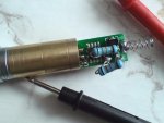
So i was really impatient till someone explain what this big resistor is for, and i decide to remove it.
Well, what i was expecting..
I blown my laser modul of course.
But i had 3 modules left with same problem with dimming so i was experimenting though.

i have figured out that i need to lover the resistance slowly..
current resistor is 0,8ohm so i have found 1,4ohm resistor and i connected it in parallel with current one.. it gave me a 0,5 ohms..
Still not good results..

Then i took resistor from my dead module which i burned because of lack of any big resistor and it gives me 0,4ohm in total..

And here it comes guys..
I HAVE GOT A STABLE OUTPUT AS YOU CANT EVEN IMAGINE...
Potentiometer is in a position as it comes from manufacture and it is supposed to be 5-10mw..
But it is sooooo damn bright that i can definitely say at least 50mw..
also there is no marks of overheating.. even resistors stays cold.. but probbably because they are two not one.. i dont know..

so i think that 0,4 ohm resistance is a way to go if you have a problem like me with dimming and not getting the stable output just from turning the potentiometer..

now all i need to do is to find a small resistor with 0,4ohms to make it fit a pen back... but probably i will need to buy it as i doubt i have one.. anyway i hope that my other 2 modules (lasers) will thread in the same way as i am not going to work on them till i have 0,4ohms resistors..

i hope that i contribute to this community just a little bit and it will help you guys too.

Thank you

Milan
 

Attachments

  • reparing the module 0,4ohms.JPG
    reparing the module 0,4ohms.JPG
    50.8 KB · Views: 128


alx

0
Joined
Jan 8, 2009
Messages
229
Points
0
Guys
now all i need to do is to find a small resistor with 0,4ohms to make it fit a pen back... but probably i will need to buy it as i doubt i have one.. anyway i hope that my other 2 modules (lasers) will thread in the same way as i am not going to work on them till i have 0,4ohms resistors..
Milan

Milan,

I don't know how you got 0.4 Ohm... As I can see from your pics, you put 2 x 0.33 Ohm resistors in parallel. Also these resistors has 1% tolerance and as I can see from the resistor case size, 1W power (each). Resulting resitance is 0.165 Ohm/2Watts AND NOT 0.4 OHM. That's you are able to find out that booth resistors remain cool... Now, almost the same power is dissipated equal on booth ... And keep in mind in case you want to replace this resistor, you need 0.165 Ohm over 2Watts, 1% tolerance ... Maybe at 0.16x Ohm, 1% tolerance will be difficult to find (an to be cheap), so you can try with 5 or 10%. About resistor power, at rates I am seeing you drive the diode, 1 watt will be enough, so you need 0.16 or 0.17 Ohm at 1 watt (minimum 0.6Watt). Look to find closer standardized value ...

Regards,
Alx
 
Last edited:
Joined
Dec 2, 2008
Messages
339
Points
18
Milan,

I don't know how you got 0.4 Ohm... As I can see from your pics, you put 2 x 0.33 Ohm resistors in parallel. Also these resistors has 1% tolerance and as I can see from the resistor case size, 1W power (each). Resulting resitance is 0.165 Ohm/2Watts AND NOT 0.4 OHM. That's you are able to find out that booth resistors remain cool... Now, almost the same power is dissipated equal on booth ... And keep in mind in case you want to replace this resistor, you need 0.165 Ohm over 2Watts, 1% tolerance ... Maybe at 0.16x Ohm, 1% tolerance will be difficult to find (an to be cheap), so you can try with 5 or 10%. About resistor power, at rates I am seeing you drive the diode, 1 watt will be enough, so you need 0.16 or 0.17 Ohm at 1 watt (minimum 0.6Watt). Look to find closer standardized value ...

Regards,
Alx

you might be right.. i dont know..
all i know is that i measured 0,7-0,8ohms on the resistor atached on the driver..
then i add another one and i get 0,4ohms..

i am going to desolder one and i will measure it alone, and not attached to anything..
I will post a results..

Milan
 
Last edited:

alx

0
Joined
Jan 8, 2009
Messages
229
Points
0
you might be true.. i dont know..
all i know is that i measured 0,7-0,8ohms on the resistor atached on the driver..
then i add another one and i get 0,4ohms..

i am going to desolder one and i will measure it alone, and not attached to anything..
I will post a results..

Milan

Milan, you forgot to take in consideration your multimeter wires resistance... and from your post above, should be around 0.3 Ohm. Just put the wires toghether (short it) and see what you can read on display...should be something over zero (0.2-0.4Ohm)... When you are working with fractions of ohms, you should be carreful about this aspect... ;-). You should look for 0.16-0.17 Ohm resistance as I said above ...

Regards,
Alx
 
Joined
Dec 2, 2008
Messages
339
Points
18
Milan, you forgot to take in consideration your multimeter wires resistance... and from your post above, should be around 0.3 Ohm. Just put the wires toghether (short it) and see what you can read on display...should be something over zero (0.2-0.4Ohm)... When you are working with fractions of ohms, you should be carreful about this aspect... ;-). You should look for 0.16-0.17 Ohm resistance as I said above ...

Regards,
Alx

thank you man..
Really appreciate it

i have desoldered it and it shoved me as i posted before.. 0,7-0,8ohms..

i have never known that i have to care about resistance of my multimeter wires.. now i will remember that forewer.

i have measured those wires to be 0,3ohms..

you are right MAN.. and you are my hero also..
i would like you to lead me throught this proces as you can see all i know is to replace it.. but i have no idea now which resistor i should buy
i have no idea about tolerance and watts.. which you have mentioned..
could you please tell me exactly what i have to ask in a shop?
all i know now is that it should be a minimum of 0,15x

also do you think will it work?
as for now it works pretty good..

Thank you in advance

Milan
 
Last edited:

alx

0
Joined
Jan 8, 2009
Messages
229
Points
0
thank you man..
Really appreciate it

i have desoldered it and it shoved me as i posted before.. 0,7-0,8ohms..

i have never known that i have to care about resistance of my multimeter wires.. now i will remember that forewer.

i have measured those wires to be 0,3ohms..

you are right MAN.. and you are my hero also..

:) you are welcome ;-)

but i have no idea now which resistor i should buy


Milan, ask at your shop what resistors have near 0.165 Ohm! 0.14, 0.15, 0.16, 0.17, 0.18...If they will give you some options, say that you want the one with bigger power. Usually, you can find 0.5W, 0.6W but better for you is to have 1Watt. Finally, if still have some options, filter by tolerance (smaller value mean better precision). And finally, still have some options, filter by case size! That's all!

also do you think will it work?
as for now it works pretty good.
Milan

If now is working good, just replacing 2 resistors with one equivalent, will not affect present setup, so sure, will work.

Regards,
Alx
 
Joined
Dec 2, 2008
Messages
339
Points
18
:) you are welcome ;-)


Milan, ask at your shop what resistors have near 0.165 Ohm! 0.14, 0.15, 0.16, 0.17, 0.18...If they will give you some options, say that you want the one with bigger power. Usually, you can find 0.5W, 0.6W but better for you is to have 1Watt. Finally, if still have some options, filter by tolerance (smaller value mean better precision). And finally, still have some options, filter by case size! That's all!


If now is working good, just replacing 2 resistors with one equivalent, will not affect present setup, so sure, will work.

Regards,
Alx


thank you very much mate.

I have also done some research about resistors and how to decode them by their color code as i showed myself here as an idiot..
Anyway i have learned something new

the biggest problem is that shop where i will go to buy those resistors is not that amazing in their services, and probably i will need to find this resistor by myself.. lol.. here is just one girl which dont know much, but it is the best store though.

i decided to go for a 0,15 or 0,16ohm values as it is the closest eqvivalent of two parallel conected 0,33ohm resistors..
now i now how my resistor code should looks like

for 0,15 Ohms brown - green - silver -- brown for a 1% tolerance or even gold for a 5%
for 0,16 Ohms brown - blue - silver -- brown for a 1% tolerance or even gold for a 5%

but, correct me if i am wrong please..
as i have met with an black line on the begining as well in some cases..

but one more thing.
how will i know if it is an 0,5 - 0,6 or 1W ???
how can i decode this ?

Cheers
and thank you

Milan
 
Last edited:

alx

0
Joined
Jan 8, 2009
Messages
229
Points
0
To learn how to decode, search by google using "resistors color code" or use this link:
Resistor Codes - Transwiki

for 0.15 Ohm (5 bars code) will be:
black (0), brown(1), green(5), silver (x0.01), brown (1% tolerance)

for 0.16 Ohm (the same, 5 bars code):
black (0), brown(1), blue(6), silver (x0.01), gold (5% tolerance)
or
black (0), brown(1), blue(6), silver (x0.01), silver (10% tolerance)

smaller case size it mean less power. look to find a resistor with simillar case size like your existing one (0.33 Ohm) ... it is over 1wat power ... maybe 1 or 2 watts. And the seller must know how these are rated. ask it!

Regards,
Alx
 
Last edited:

jeffd

0
Joined
Jun 25, 2009
Messages
540
Points
0
The resistor color code is:
black = 0
brown = 1
red = 2
orange = 3
yellow = 4
green = 5
blue = 6
violet = 7
grey = 8
white = 9

The first two color bands you read as the numbers, and the third band is how many zeros are after them.
 
Joined
Jul 1, 2009
Messages
1,679
Points
0
I got my third one open today. It came out of box at 246mA. I don't have my meter yet, so I'm not sure what it was putting out. I cranked it up to 360mA. We'll see how long it lasts at that current.
 

seoguy

0
Joined
Feb 9, 2009
Messages
263
Points
0
Well, I got my new True 5 last week. And if the first one was too wimpy...this new one made up for it!

Measured 270ma at factory setting! And definitely WAY over 5mw!!! :yh:

I heard they were having a shortage of low-power modules & pens around that time - I can't help but wonder if they just shipped me a higher-power one instead???

This thing is BRIGHT - spot is so bright that it kinda hurts your eyes just to look at it! Beam barely visible in well-lit room during the DAY (albeit a cloudy day), and clearly visible in a moderately-lit room. DEFINITELY good visibility at night - if fairly dark area, looks solid all the way up to the sky!

Beam also clearly visible at night horizontal (not just against a dark sky), and if bounced-off a fence or object from an angle, will actually cast light on nearby objects, like a damn laser flashlight! :cool:

Comparative tests with my homemade optical sensor, and my homemade thermal sensor, both put it at about 3.5x brighter than my eBay 10mw (which I suspect is brighter than 10).

I haven't decided if having them turned-up this high from the factory is good or bad yet. There's not much further I could pot-mod it, and it could be a badly-aligned unit that they had to turn-up that high just to get a beam??? Or it could be a True 50 they sent by mistake or because they were out of 5's?

I'm a bit hesitant to tear it apart though - because it works so sweet just the way it is! ;)

Definitely makes-up for the crappy one they sent me the first time though!

Also gives me incentive to crank that other one up now - and that one has a LOT of room for growth, as the first one was only set to 170ma!

Had also been waiting for my goggles, but they just came in - broken! :cryyy:

(My first experience with FocalPrice is not turning-out to be a good one. They were also actually slower at shipping than DX! :yabbmad:)


@bryce007:

it was 254ma out of box, but it definitely was over 5mw. I don't have my meter yet, but I would say it was about 20-25mw out of box.

Sounds like yours is similar to what I just got!

I got my third one open today. It came out of box at 246mA. I don't have my meter yet, so I'm not sure what it was putting out. I cranked it up to 360mA. We'll see how long it lasts at that current.

Damn, do you think that poor little diode can go up that high? How bright would you say it was originally, compared to the other one?


@john_lawson:

@ seoguy i havent taken the lenses apart on any yet

If you have any of the new ones with the wide threaded end, it's easy! The 3 brass pieces just screw-apart, they're not even on there tight, unscrews easily with no effort!

DEFINITELY not as hard as getting them out of the host! :rolleyes:

i just give it a small ccw turn

These drivers have a VERY wide range, so a little turn goes a long ways - my 100mw is factory-set at 530ma - and the pot isn't even turned-up halfway!

hey this is the first time i had a thread go this long
I feel important now

Glad we could make you feel important! LOL ;)
 

seoguy

0
Joined
Feb 9, 2009
Messages
263
Points
0
Greendream, milantheone - have some detailed posts I need to finish-up for you both, but I need to get a ltl shut-eye first! :tired:

Especially milantheone, I have a LOT of information for you - you're gonna want to hold-off on making any resistor selections until you get a chance to read what I have to say! ;)
 
Joined
Jul 1, 2009
Messages
1,679
Points
0
@seoguy, I'm pretty sure that John meant that he hasn't taken the lenses out. Like taking just the lens out so you can focus it better.
 
Joined
Jul 27, 2009
Messages
120
Points
0
seoguy - same here. Will try to post some more data/pics here soon, but I've been up to my eyeballs recently, so not sure exactly when.
 
Joined
Dec 2, 2008
Messages
339
Points
18
Greendream, milantheone - have some detailed posts I need to finish-up for you both, but I need to get a ltl shut-eye first! :tired:

Especially milantheone, I have a LOT of information for you - you're gonna want to hold-off on making any resistor selections until you get a chance to read what I have to say! ;)


Thank you MAN

hope it will be about aligning proces, and if you have some info about changing the resitors i am definitely for them..

Anyway i have repaired some of my units with chaning the resistor, but it doesnt work for all..
Now i am sure that it was just a little luck.. there is probably NO reasonable need for changing them.. but probably you will bring a light to this..

i cant wait..

Cheers..

Milan


Top