Welcome to Laser Pointer Forums - discuss green laser pointers, blue laser pointers, and all types of lasers

LPF Donation via Stripe | LPF Donation - Other Methods

Links below open in new window

ArcticMyst Security by Avery

Where's the "battery intake" on the C6?

Joined
Feb 18, 2012
Messages
796
Points
28
Hey guys,

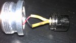
Now that all my parts are here, I've gone ahead to build my first laser with a C6 host.

I have everything set up (I think) but my laser's not lasing. I went ahead to recharge my batteries which are brand new and am waiting for a full charge atm.
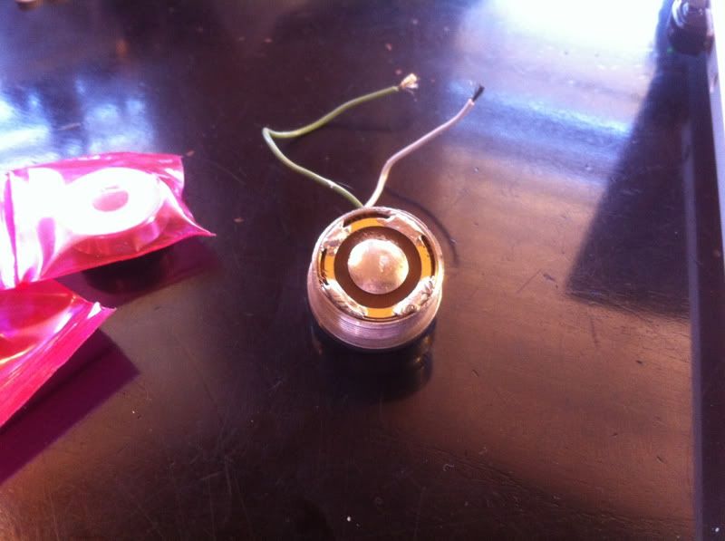
For now, I want to make sure, is this, IMAG0093-1 (780x598).jpg, the underside of the CREE driver, also the positive battery contact?

Regards,
 

Attachments

  • IMAG0092 (800x451).jpg
    IMAG0092 (800x451).jpg
    262.9 KB · Views: 197


Joined
Aug 14, 2011
Messages
1,109
Points
0
It's the positive contact if you made it the positive contact. ;)

Normally yeah, that's how people set it up.

Edit: middle is positive, outer ring in negative.
 
Last edited:
Joined
Aug 14, 2011
Messages
1,109
Points
0
^^ The battery + shouldn't make contact with it, you should be ok. Yo can make a connection from the outer ring on the driver to the brass retaining ring though, which is in contact with the pill, which connects to the host, which is negative.
 
Last edited:
Joined
Nov 19, 2011
Messages
294
Points
0
It gets the ground from the host. Make sure the brass retaining ring is soldered to the pill and the driver board.

0b5173e8.jpg


Glenn

Edit: Ghostchrome was faster, but mine has a pic! :na:
 
Last edited:
Joined
Feb 18, 2012
Messages
796
Points
28
Before connecting the driver to the diode, I just touch the 2 driver wires together right? Nothing I need to do to the diode? What about order of soldering? Positive first or negative first?

Also, Gatkins, I see you solder the middle of your driver, is this needed?
 
Joined
Feb 18, 2012
Messages
796
Points
28
Hmm.. after soldering the driver to the brass ring, my laser still can't turn on. This is really frustrating, what am I doing wrong?

I don't have to adjust current on the driver right? It comes standard at 1.2A?

Man what else am I missing? Like jesus I don't even know what's wrong, is my diode dead? My driver dead? Ughh... I followed this tutorial mostly

Wait, is it Pill -> Driver -> Brass ring
Or Pill -> Brass ring -> Driver ?

Cause I set it up Pill -> Driver -> Brass ring on top
and now I can't change it up cause I soldered the ring and driver already. OMG I'm going to snap this is so frustrating.
 
Last edited:

Blord

0
Joined
Dec 24, 2007
Messages
5,356
Points
0
Make sure that the brass ring is making contact with the pill and with the outer ring of the PCB. Check it with a DMM. You do have one ?

You don't need to solder a blob to the middle of the PCB. And check the wires from the driver to the diode, driver+ to diode+ and driver- to diode- .

Did you use two 16340/18350 batteries for the C6 ?
 
Last edited:
Joined
Nov 19, 2011
Messages
294
Points
0
That particular board came stock from Mohrenberg with the solder in the middle of the board to help contact the positive battery terminal.

Glenn
 
Joined
Feb 18, 2012
Messages
796
Points
28
Make sure that the brass ring is making contact with the pill and with the outer ring of the PCB. Check it with a DMM. You do have one ?

You don't need to solder a blob to the middle of the PCB. And check the wires from the driver to the diode, driver+ to diode+ and driver- to diode- .

Did you use two 16340/18350 batteries for the C6 ?

2 16340s. I used thermal epoxy between the driver and pill and driver and pill and brass ring. Is this what's wrong?
 

Blord

0
Joined
Dec 24, 2007
Messages
5,356
Points
0
Remove the epoxy. It is preventing electrical contact with the pill.

The correct method is put the 17mm round driver into the brass ring and soldered it together. Then press it into the aluminium pill.
All the three pieces must be flush. No need for epoxy/paste.
 
Last edited:
Joined
Feb 18, 2012
Messages
796
Points
28
Ok so I just started my 2nd build since I can't remove the solder from the 1st driver & brass ring.

And now on my 2nd build, I fixed it correctly in order, but when I turned it on, the laser turned on for 0.1s and then off and wasn't able to turn on again. WHat the hell happened now?
grr Spending 5 hrs now.....
 
Joined
Dec 27, 2011
Messages
2,062
Points
48
You have any pics? Maybe you could take pics each step of the way and someone could maybe spot a glitch?
 
Joined
Feb 14, 2012
Messages
479
Points
0
check inside the clicker cap. It may need to be tightened or loosened. Had the same issue with mine. Also make sure you didnt twist the wires when you screwed down the heatsink.
 
Last edited:

Blord

0
Joined
Dec 24, 2007
Messages
5,356
Points
0
Looks like your diode is fried.

Do you have a testload ? This device can save you time and money. You don't have to waste a diode for every attempt.
 
Joined
Feb 18, 2012
Messages
796
Points
28
Looks like your diode is fried.

Do you have a testload ? This device can save you time and money. You don't have to waste a diode for every attempt.

Yes I have a testload but I don't know how to use it.

And how did I fry my diode? I touchd the driver wires together b4 connecting (like I should right?) What else do I need to do? Like I need to know what the hell I'm doing wrong cause I just washed over $100 down the drain. 2 diodes, 2 cree drives, 1 brass ring, and a shitload of time.

God am I retarded or are first builds really this frustrating.


Top