

JLSE
1
- Joined
- Dec 13, 2007
- Messages
- 3,580
- Points
- 0
Okay, I etched out some boards for the lm 3410. I must first thank 'woop' for posting his thread for this nice little boost circuit.
I am trying to figure out the value of the inductor. In woops board and the pdf for the 3410 it calls for a 4.7uH inductor, now on the cheap side, seeing as I am just trying this out, I would like to find the value to some inductors that I already have.
After discussing this with a few people I have found that there is no universal markings on these components. Inductors are marked by the manufacturer with whatever they feel, and there is no way for the average test equipment to find this value. Hopefully that is wrong, and there is a way to find it.
The inductors I have are marked -22 ON-, anyone have an idea for their value? I got these from a local surplus outlet for free and have approx 50 of them, hence the desire to use them. From what I found the 4.7uH inductors are labeled 33. Is there enough tolerance with the 3410 to use the coils I have? I dont want to blow any parts, but will if I must.
Here is a pic of the first set etched. I am still working out the kinks in the etch for these tiny boards.
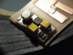


 It was the only board I didnt check the trace after etching.... Still smoothing out the etch process ;D


