Welcome to Laser Pointer Forums - discuss green laser pointers, blue laser pointers, and all types of lasers

LPF Donation via Stripe | LPF Donation - Other Methods

Links below open in new window

ArcticMyst Security by Avery

Short question

Joined
Sep 7, 2007
Messages
634
Points
0
Gazoo I think you have already told me this. Once I have everything soldered in for my LD, hooked to Daedal's circuit, how do I monitor the current. You said something about a resistor and put the multimeter on voltage setting. Where do I put this resistor?


Joined
Feb 1, 2007
Messages
810
Points
0
Death Angel, set you multimeter to measure amps not voltage. to accurately measure current you must break the circuit and connect the multimeter in the gap.. Current is a measurement of flow so you must connect your multi meter in SERIES with the circuit.

This little diagram will explain. the "A" in the circle represents your multi meter.

Jase
 

Attachments

  • ammeter_001.gif
    ammeter_001.gif
    16.6 KB · Views: 81

Gazoo

0
Joined
Jun 9, 2007
Messages
3,206
Points
38
Tallaxo,
There is a much better and safer way to determine current. Please read through the thread for the link I posted above.
 
Joined
Sep 7, 2007
Messages
634
Points
0
Oh now I remember that topic. Duh I posted it. :p 
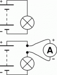
So I should just solder the 1 ohm resistor in series with the LD? Meaning one end to the capacitor and the other to one side of the LD.
 

Gazoo

0
Joined
Jun 9, 2007
Messages
3,206
Points
38
Yup.. :) The resistor can be soldered in series before or after the capacitor, whichever is easiest for your circuit. Then measure voltage across the resistor with the voltage setting of your meter, and it will give you the same reading as if you were measuring current.
 
Joined
Sep 7, 2007
Messages
634
Points
0
Okay got it now Gazoo. Thanks. Would this be a good permanent setup? With the resistor I mean. Probably wouldn't harm anything being only a 1 ohm. Oh and another thing. When I do solder everything from Daedal's circuit, could I replace the 25 ohm rheostat with a resistor equivalent to the rheostat's resistance at the point at which I find proper current to the LD? I just wouldn't be able to fit that big rheostat in a Dorcy mini or whatever else.
 
Joined
Jan 7, 2007
Messages
6,309
Points
83
Replacing the 25 ohm pot with a fixed resistor will work. Be sure to use a high enough wattage device --- Pw = I^2 x R

Eg: 250 mA with 5 ohms => .0625 x 5 = .31 Watts == Use a half watt resistor.

Mike
 

Gazoo

0
Joined
Jun 9, 2007
Messages
3,206
Points
38
Death Angel said:
Okay got it now Gazoo. Thanks. Would this be a good permanent setup? With the resistor I mean. Probably wouldn't harm anything being only a 1 ohm. Oh and another thing. When I do solder everything from Daedal's circuit, could I replace the 25 ohm rheostat with a resistor equivalent to the rheostat's resistance at the point at which I find proper current to the LD? I just wouldn't be able to fit that big rheostat in a Dorcy mini or whatever else.

Yes, you can measure the resistance of the rheostat when you find the current you want to operate at. BUT, if you plan on mounting in a flashlight, then measure the current with the 1 ohm resistor removed because it does drop the current, and is another component that is not needed.
 
Joined
Jan 7, 2007
Messages
6,309
Points
83
Gazoo --

We are covering several ideas here. The question I answered related to the substitution of a fixed resistor in place of the 3 watt , 25 ohm pot to save space.
Your 1 ohm resistor is a good idea - I may do that on mine too.

Mike
 

Gazoo

0
Joined
Jun 9, 2007
Messages
3,206
Points
38
Mike I apologize...I realized what you were saying after rereading your post so I deleted mine...sorry.. :p
 
Joined
Jul 20, 2007
Messages
220
Points
0
the current regulator should be precise enough to use this formula: 1.25/resistance=current just make sure with a multimeter and if you see that everything is okay it should work fine.


Top